Eureka AIR delivers breakthrough ideas for toughest innovation challenges, trusted by R&D personnel around the world.

High-sealing air seal machine and drying equipment

A high-sealing and air-closing technology, which is applied to dry solid materials, dry cargo handling, lighting and heating equipment, etc., can solve the problems of reduced sealing area, uneven sealing surface, and easy wear and tear of sealing devices

Inactive Publication Date: 2021-07-30
MENGZHOU YUANHONG DRYING EQUIP RES & DEV CO LTD
View PDF0 Cites 0 Cited by
  • Summary
  • Abstract
  • Description
  • Claims
  • Application Information

AI Technical Summary

Problems solved by technology

3. Under the heavy pressure of the external force when the sealing device is adhered, the force of the sealing device at different positions is uneven. After the glue is solidified, some places of the sealing device are raised and some are sunken, resulting in the outer sealing surface of the sealing device is uneven
5. The impeller after fixing the sealing device is not machined to meet the precision requirements of cylindricity and surface profile
6. The sealing surface of the sealing ring is convex, which reduces the sealing area
7. The cylindricity and surface profile of the outer circular sealing surface of the sealing device fixed on the impeller do not meet the accuracy requirements, and there are different distances between the uneven sealing surface on the outer circular surface of the sealing device and the inner wall of the valve. gap, the air lock performance of the air lock is greatly reduced
[0005] There are many problems with the air locks used in the drying equipment on the market. Due to the small sealing surface between the sealing device of the air lock and the inner wall of the valve, many problems of wear and tear have not been solved, resulting in dry air in the market. The air-tightness of the air lock used in the equipment is poor, and the sealing device is easy to wear, which will eventually cause a large amount of air leakage and affect the drying processing efficiency of the drying equipment

Method used


Image

  • High-sealing air seal machine and drying equipment
  • High-sealing air seal machine and drying equipment
  • High-sealing air seal machine and drying equipment

Examples


Embodiment 1

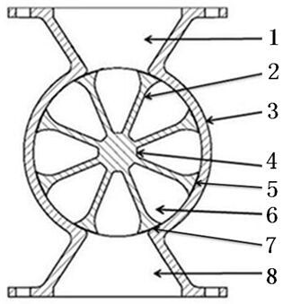
[0044] Such as figure 1 , figure 2 , image 3 As shown: a high-seal type air shut-off device includes a valve casing, an impeller 4, and a sealing device 7.

[0045] The valve casing includes a valve body 3, a side cover, and a bearing. Bearing is installed in the center position of side cover, and two side covers are fixed on the both sides of valve body 3.

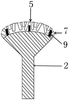
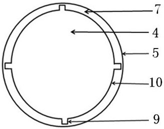
[0046] The valve casing has a feed port 1 and a discharge port 8. The inner wall of the valve body 3 is smooth, and the side cover next to the baffle plate 10 is flat and smooth.

[0047] The impeller 4 includes a vane 2, a baffle 10, and a transmission shaft.

[0048] The blade plate 2 and the baffle plate 10 are fixed on the drive shaft, the blade plate 2 is fixed between the two side baffle plates 10, the number of the blade plate 2 is 8, the baffle plate 10 is two, and the quantity of the feed bin is 8.

[0049] Such as image 3 The shown limiting block 9 and the impeller 4 are integral structures, and the m...

Embodiment 2

[0058] Such as figure 1 A high-seal type air shutoff shown includes a valve casing, an impeller 4 and a sealing device 7 .

[0059] The similarities between the high-seal type air locker in Embodiment 2 and the high-seal type air locker introduced in Embodiment 1 will not be repeated here.

[0060] Such as figure 1 There is no groove on the sealing device 7 shown, and there is no limit block 9 on the impeller 4;


PUM

PropertyMeasurementUnit
Thicknessaaaaaaaaaa

Abstract

The invention discloses a high-sealing air seal machine, comprising a valve shell, an impeller and a sealing device. The outer circle sealing surface of the sealing device fixed to the impeller is subjected to turn milling or grinding, and the surface profile tolerance of the outer circle sealing surface of the sealing device meets the requirement for high sealing use precision of a small gap between the sealing surface of the sealing device and the inner wall of a valve body. The smooth outer circle sealing surface of the sealing device is fully attached to the inner wall of the valve body, and the sealing area between the sealing device and the inner wall of the valve body is enlarged. The impeller, the valve body and the side cover are dynamically sealed through the sealing device, so that the air locking performance of the air seal machine is greatly improved. According to the drying equipment, the high-sealing air seal machine is used in cooperation, the high-sealing air seal machine can conduct high-sealing feeding and discharging in the environment with the high pressure difference inside and outside a drying bin of the drying equipment, and it is guaranteed that the drying equipment conducts effective drying work.

Description

technical field [0001] The invention relates to the field of drying equipment, in particular to a high-seal type air lock and drying equipment. Background technique [0002] Air shut-off device is also called shut-off fan, unloading valve, ash unloading valve and star unloading device. The installation of the present air lock is cumbersome, the structure is complex, and the production is difficult. When the impeller rotates in the valve body to convey material or gas, there is a certain gap between the sealing device fixed on the impeller and the inner wall and side cover of the valve body, and the size of the gap is an important factor for evaluating the gas locking performance. [0003] The shape and structure of the sealing device currently used is mostly a sealing strip or a sealing block. 1. The outer circular sealing surface of such a sealing device is a round surface or a plane, and the outer sealing surface of the sealing device is only attached to the inner wall of...

Claims


Application Information

Patent Timeline
IPC IPC(8): B65G53/46B65G53/36B65G53/34F26B25/00
CPCB65G53/34B65G53/36B65G53/4625F26B25/002
Inventor 程长青
Owner MENGZHOU YUANHONG DRYING EQUIP RES & DEV CO LTD
Why Eureka
Eureka Blog
Learn More