
Semi-open type drill rod for deposition sampling and using method of semi-open type drill rod

A semi-open, drill pipe technology, applied in drill pipe, sampling device, drill pipe, etc., can solve the problems of high economic cost, difficulty in identifying sedimentary structures, and difficulty in taking out PVC pipes.

Pending Publication Date: 2021-07-30
CHINA UNIV OF PETROLEUM (BEIJING)
View PDF0 Cites 0 Cited by
  • Summary
  • Abstract
  • Description
  • Claims
  • Application Information

AI Technical Summary

Problems solved by technology

[0005] However, the disadvantages of adopting the sampling method of the inner plug PVC pipe are: 1) the sampling efficiency is low. In order to prevent the deformation of the PVC pipe, only 1-2m (1-2 drill pipes) depth can be continuously drilled each time. It is difficult to take out the PVC pipe from the drill pipe. When encountering sticky sediment, it is difficult to pour the sediment directly from the PVC pipe, and it needs to be cut directly with a knife. Because the hardness of the PVC pipe is high, it is difficult to cut it; 2) It cannot be continuous During drilling, if a water-bearing sand layer is encountered, the hole is likely to collapse, and the impact of the collapse on the vertical sequence of sediments needs to be considered when drilling again; 3) The operation of cutting the PVC pipe with a knife is dangerous, and The section of PVC is relatively sharp, and it is easy to scratch when sampling in the field; 4) The section of the sediment that is cut with a knife is not straight and beautiful; Higher; 6) The inner diameter of the drill pipe is only about 50mm. After the PVC pipe is plugged in, the sampling diameter is further reduced. The smaller the sampling diameter, the smaller the sampling volume, and the more difficult it is to identify the sedimentary structure

Method used


Image

  • Semi-open type drill rod for deposition sampling and using method of semi-open type drill rod
  • Semi-open type drill rod for deposition sampling and using method of semi-open type drill rod
  • Semi-open type drill rod for deposition sampling and using method of semi-open type drill rod

Examples


Embodiment Construction

[0040] In order to make the purpose, technical solution and advantages of the present invention clearer, the technical solution of the present invention will be clearly and completely described below in conjunction with the accompanying drawings. Apparently, the described embodiments are some, but not all, embodiments of the present invention. Based on the embodiments of the present invention, all other embodiments obtained by persons of ordinary skill in the art without making creative efforts belong to the protection scope of the present invention.

[0041] In the description of the present invention, it should be noted that the orientation or positional relationship indicated by the terms "upper", "lower", "inner", "outer" and the like are based on the orientation or positional relationship shown in the accompanying drawings, and are only for It is convenient to describe the present invention and simplify the description, but does not indicate or imply that the system or el...


PUM


Abstract

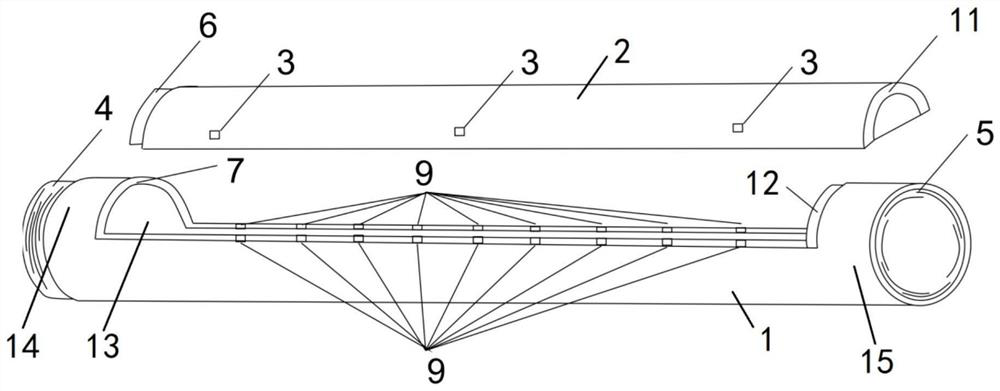
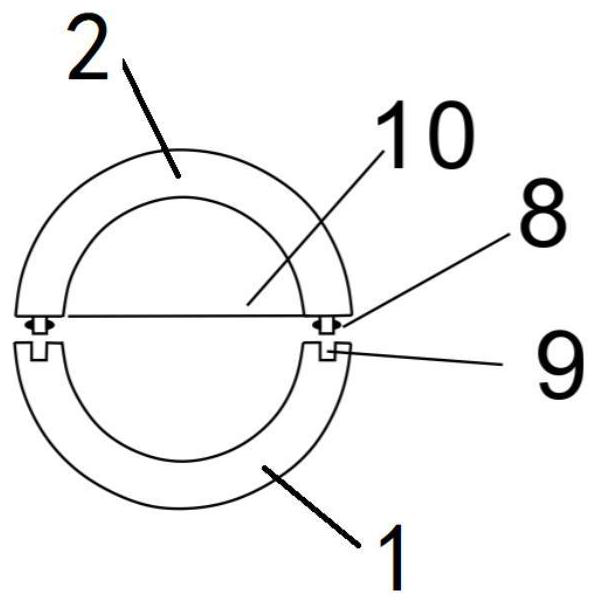
The invention relates to a semi-open type drill rod for deposition sampling. The semi-open type drill rod comprises a drill rod main body and a sealing plate, wherein the drill rod main body is a cylindrical body, the side wall of the cylindrical body is provided with a notch along the length direction of the drill rod, the sealing plate is a semi-cylindrical shell, the semi-cylindrical shell matches with the notch in the drill rod main body, the semi-cylindrical shell and the notch in the drill rod main body are detachably spliced to form a closed cylindrical drill rod, a separation cutter plate is connected between the two sides of the bottom of the sealing plate, and the separation cutter plate is located in the central plane. According to the semi-open type drill rod, the sampling efficiency can be better improved, the sampling difficulty and dangerousness are reduced, the attractiveness of the section of sediment is improved, the sampling amount is increased, the cost is saved, and waste is avoided.

Description

technical field [0001] The invention relates to the technical field of sedimentary facies drilling and sampling, in particular to a semi-open drill pipe used for sedimentary sampling and a usage method thereof. Background technique [0002] Sedimentary facies is a combination of the depositional environment and the characteristics of the sedimentary rocks (objects) formed in this environment. Modern sedimentary research focuses on the macroscopic distribution and internal characteristics of sedimentary facies by analyzing the material composition, formation process, and planar distribution of modern sediments. Scholars at home and abroad have studied the deposits of modern rivers (such as the Yellow River, Mississippi River, and Amazon River), deltas (such as the Mississippi River Delta, Yangtze River Delta, and Ganjiang Delta), lakes (such as Poyang Lake, Qinghai Lake), and oceans (such as the Gulf of Mexico). A large number of studies have been carried out on these facies...

Claims


Application Information

Patent Timeline
IPC IPC(8): E21B17/00G01N1/08
CPCE21B17/00G01N1/08Y02A90/30
Inventor 徐振华吴胜和岳大力张佳佳李庆
Owner CHINA UNIV OF PETROLEUM (BEIJING)
Learn More