
Part repairing workbench and workbench using method

A workbench and parts technology, which is applied in the field of parts repair workbench, can solve the problems of large influence on measurement accuracy, poor measurement stability, and low measurement efficiency, so as to improve efficiency, facilitate repair operations, and reduce labor intensity.

Pending Publication Date: 2021-07-30
CHENGXI SHIPYARD
View PDF0 Cites 0 Cited by
  • Summary
  • Abstract
  • Description
  • Claims
  • Application Information

AI Technical Summary

Problems solved by technology

[0003] In addition, for some parts with a large number of repairs, the measurement of the inner diameter of the parts used to be carried out with general measuring tools. The measurement accuracy is greatly affected by the skills of the operator, the measurement stability is poor, and the measurement efficiency is also relatively low Low

Method used


Image

  • Part repairing workbench and workbench using method
  • Part repairing workbench and workbench using method
  • Part repairing workbench and workbench using method

Examples


Embodiment 1

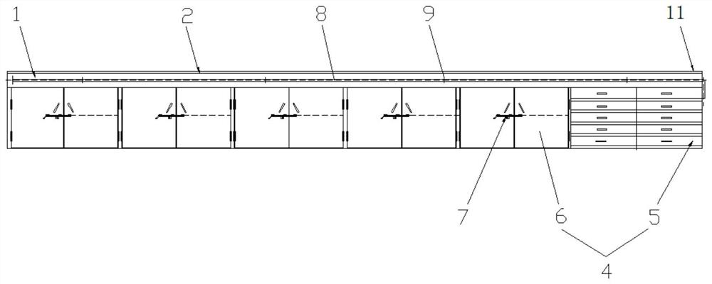
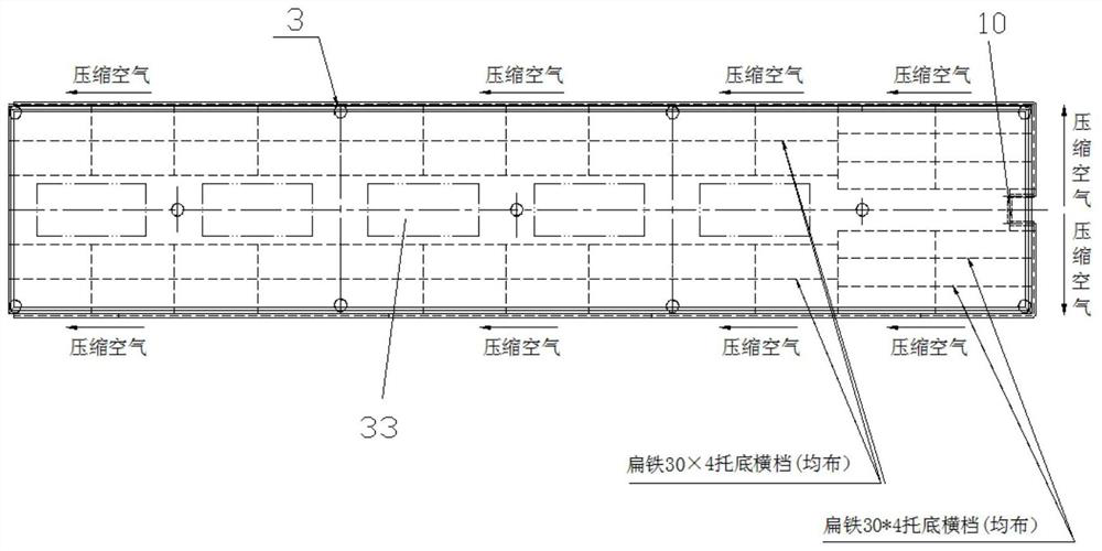
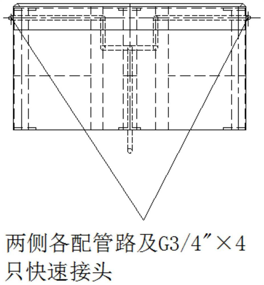
[0035] Such as Figures 1 to 4 Shown is an embodiment of a part repair workbench of the present invention, which includes a main body 1 of the worktop, a stainless steel cladding plate 2 laid on the main body 1 of the worktop to form the surface of the repair workbench, and a workbench arranged under the main body 1 of the worktop. A table column 3, a number of tool cabinets 4 are arranged adjacent to the bottom of the table main body 1 in turn; wherein, at least one tool cabinet 4 in the tool cabinet 4 is set to a drawer-type tray 5 structure; except for the drawer-type tray 5 Outside the tool cabinet 4 of the structure, the remaining tool cabinets 4 adopt a double-open or single-open cabinet door 6 structure, and the double-open or single-open cabinet door 6 structure is provided with a cabinet door handle lock pin attachment 7; A compressed air pipeline 8 is arranged on the circumferential side of the main body 1 , and a number of quick connectors 9 are arranged at interval...

Embodiment 2

[0048] A method for using the workbench using the part repair workbench of Embodiment 1, including using the pneumatic go-no-go gauge unit 12 on the repair station to quickly detect the inner hole of the part 35, and the detection method is as follows:

[0049] (1) Calibration before measurement: According to the part 35 to be tested, select the calibration comparison circle 27 corresponding to the inner diameter of the same specification, insert the cylindrical pneumatic probe 15 into the inner hole of the calibration comparison circle 27, and perform the cylindrical pneumatic probe 15 The accuracy correction;

[0050] (2) Parts installation: the parts to be detected are placed in the detection position of the repair station, so that the telescopic rod 17 of the servo electric push rod 16 is placed in the approximate central part of the inner hole of the part, and a block 24 of equal height is placed under the part if necessary; Adjust the height of the top of the telescopic ...


PUM


Abstract

The invention relates to the technical field of ship repair, in particular to a part repair workbench and a workbench using method. The part repairing workbench comprises a workbench surface main body, a stainless steel covering plate and workbench stand columns, wherein the stainless steel covering plate is laid on the workbench surface main body to form a repairing workbench surface, the workbench stand columns are arranged below the workbench surface main body, and a plurality of tool cabinets are sequentially and adjacently arranged below the workbench surface main body, and at least one tool cabinet in the tool cabinets is of a drawer type tray structure; except for the tool cabinet of a drawer type tray structure, the other tool cabinets are of a double-open type or single-open type cabinet door structure, and cabinet door handle lock pin accessories are arranged on the double-open type or single-open type cabinet door structure; and a compressed air pipeline is arranged in the circumferential side face of the table top body, and a plurality of quick connectors are arranged on the compressed air pipeline at intervals. According to the part repairing workbench and the workbench using method, the labor intensity of operators is reduced, and the efficiency and quality of repair operation are improved.

Description

technical field [0001] The invention relates to the technical field of ship repair, in particular to a part repair workbench and a method for using the workbench. Background technique [0002] For a long time, the measurement and repair of main and auxiliary machine parts (such as cylinder head, rocker arm seat, intake and exhaust valve rod, connecting rod, etc.) in the company's ship repair workshop have been performed on the ground or on the ground pad. The waist operation brings a large fatigue load to the body. During the construction process, the non-centralized and fixed-point placement of the tools causes serious waste in the production preparation process, and the scattered parts are placed randomly without fixed points, which is inconvenient to identify. Dirty, messy, poor. For this reason, it is necessary to design and manufacture the main and auxiliary machine parts repair workbench to solve the above problems. [0003] In addition, for some parts with a large n...

Claims


Application Information

Patent Timeline
Patent Type & Authority Applications(China)
IPC IPC(8): G01B5/12
CPCG01B5/12
Inventor 徐小明任强
Owner CHENGXI SHIPYARD
Learn More