
Testing equipment and testing method for mobile phone circuit chip

A technology of circuit chips and testing equipment, which is applied in the field of testing equipment for mobile phone circuit chips, and can solve problems such as poor contact detection results, errors, and insufficient contact between chips and probes

Active Publication Date: 2021-07-30
深圳市磐锋精密技术有限公司
View PDF12 Cites 3 Cited by
  • Summary
  • Abstract
  • Description
  • Claims
  • Application Information

AI Technical Summary

Problems solved by technology

[0005] In order to make up for the deficiencies of the existing technology, when the chip is tested, the probe and the pin of the chip are generally used for contact measurement, but when the chip is placed in the detector, the contact between the chip and the probe is not close enough, and contact is easy to occur The problem of the situation that the detection result is wrong caused by the defect, a kind of testing equipment and testing method of the mobile phone circuit chip proposed by the present invention

Method used


Image

  • Testing equipment and testing method for mobile phone circuit chip
  • Testing equipment and testing method for mobile phone circuit chip
  • Testing equipment and testing method for mobile phone circuit chip

Examples


Embodiment 1

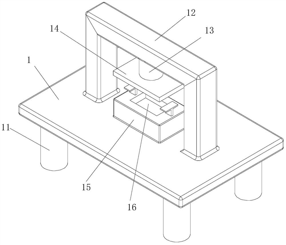
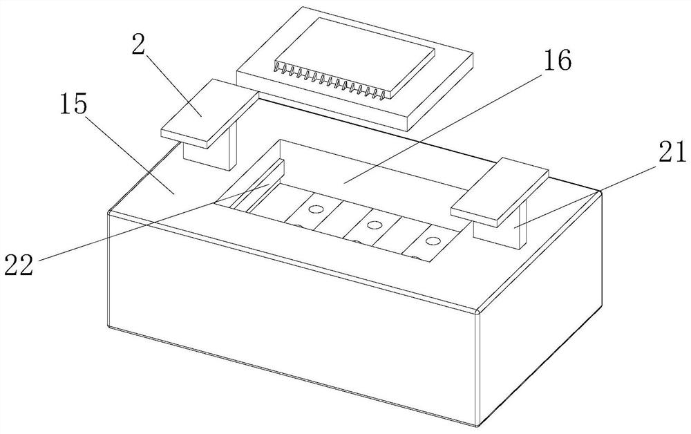
[0036] Such as Figure 1 to Figure 6 As shown, the testing equipment of a kind of mobile phone circuit chip of the present invention, comprises fixed plate 1; Described fixed plate 1 bottom end is affixed with a group of legs 11; Described fixed plate 1 is affixed with bracket 12; The support 12 is an inverted U-shaped support 12; the center of the bottom end of the support 12 is affixed with a first cylinder 13; the output end of the first cylinder 13 is affixed with an upper detection seat 14; the fixed plate 1 is relatively The position of the upper detection seat 14 is fixedly connected with the lower detection seat 15; the top of the lower detection seat 15 is provided with a placement groove 16; the lower detection seat 15 is provided with a first cavity 19; the first cavity 19 Located below the placement groove 16; the inner wall of the first cavity 19 is slidably connected with a motherboard 191; the top of the motherboard 191 is fixed with a probe 192; the bottom of t...

Embodiment approach

[0037] As an embodiment of the present invention, a pair of lower pressure grooves symmetrical to the placement groove 16 are opened on the top of the lower detection seat 15; A trapezoidal plate 21 is fixedly connected to the end, and the sloped end of the trapezoidal plate 21 extends into the first cavity 19; the sidewalls on both sides of the placement groove 16 are fixedly connected with a positioning plate 22 by a spring, and the side walls of the positioning plate 22 A push post 23 is fixedly attached to the wall; the end of the push post 23 away from the position adjustment plate 22 extends into the first cavity 19, and the end of the push post 23 contacts with the slope of the trapezoidal plate 21; during work, Generally, the size of the placement groove 16 is set to be the same as the size of the chip, which is convenient for the alignment detection of the probe 192 and the chip, but it is necessary to set up a take-out assembly to take it out, which increases the cost...

Embodiment 2

[0044] Such as Figure 7 to Figure 8Shown, a kind of testing equipment of mobile phone circuit chip of the present invention, all offer through groove 5 on the two side walls of described corrugated groove 3 bosses, and through groove 5 and through cavity 38 communicate with each other; Described through groove 5 is fixedly connected with a fixed rod 51, and the center of the fixed rod 51 is rotatably connected with a first rotating shaft 52; There is a first gear 53; the push rod 39 is affixed with a rack layer on the side wall close to the first gear 53; the first gear 53 and the rack layer are meshed with each other; during work, the push rod 39 is on the second When the roller 37 and the vertical plate 34 move back and forth, the push rod 39 can drive the first rotating shaft 52 to rotate through the mutual engagement of the rack layer and the first gear 53, and the rotation of the first rotating shaft 52 can drive the fan blade The 54 rotation can not only drive the rapi...


PUM


Abstract

The invention belongs to the technical field of chip detection, and particularly relates to mobile phone circuit chip testing equipment, which comprises a fixing plate, wherein a first air cylinder is fixedly connected to the center of the bottom end of a bracket, the output end of the first air cylinder is fixedly connected with an upper detection seat, a lower detection seat is fixedly connected to the position, opposite to the upper detection seat, of the fixing plate, a placement groove is formed in the top end of the lower detection seat, and a first cavity is formed in the lower detection seat. According to the testing method of the mobile phone circuit chip, the chip is placed in a testing placement groove to be detected; when the mobile phone circuit chip is tested through the testing method, the testing position of the mobile phone circuit chip is adjusted through a position adjusting plate, so that the measuring accuracy is guaranteed; and through folding of the upper detection seat and the lower detection seat, the mobile phone circuit chip is ensured to be in a dust-free detection state, so that the problem that when the chip is placed in a detection machine, the contact between the chip and a probe is not tight enough, poor contact easily occurs, and a detection result is wrong is solved.

Description

technical field [0001] The invention belongs to the technical field of chip detection, in particular to a test device and a test method for a mobile phone circuit chip. Background technique [0002] Mobile phone chips usually refer to chips used in mobile phone communication functions, including baseband, processor, coprocessor, RF, touch screen controller chip, Memory, wireless IC and power management IC, etc. Before the chip is packaged at the factory, it is necessary to check whether the performance of the mobile phone chip itself meets the requirements for use. Mobile phone chip testing is an important step. [0003] There are also some technical solutions for chip detection in the prior art. For example, a Chinese patent with application number 202010816916X discloses a chip test socket, including a test socket body, the upper end of which is provided with a support plate, The outer surface of the support plate is provided with a vertical connection port, and one side ...

Claims


Application Information

Patent Timeline
IPC IPC(8): G01R31/28G01R1/04B08B1/00
CPCG01R31/2856G01R31/2865G01R1/0425B08B1/12
Inventor 曾风平刘文杨传奇徐思通赵阳吴继承何杰
Owner 深圳市磐锋精密技术有限公司
Learn More