
Calibration device of optical waveguide display module

A technology of a display module and a calibration device, applied in the field of assembly and manufacturing, can solve the problems of difficult adjustment and low yield rate, etc.

Pending Publication Date: 2021-07-30
ZHEJIANG CRYSTAL OPTECH
View PDF0 Cites 0 Cited by
  • Summary
  • Abstract
  • Description
  • Claims
  • Application Information

AI Technical Summary

Problems solved by technology

[0004] In the current technology, when the optical waveguide element and the imaging system are calibrated and assembled and fixed, the relative position between the two is generally adjusted manually, which is difficult to adjust and the yield rate of the product is low.

Method used


Image

  • Calibration device of optical waveguide display module
  • Calibration device of optical waveguide display module
  • Calibration device of optical waveguide display module

Examples


Embodiment Construction

[0026] In order to make the purposes, technical solutions and advantages of the embodiments of the present application clearer, the technical solutions in the embodiments of the present application will be described clearly and completely below with reference to the drawings in the embodiments of the present application. Obviously, the described embodiments It is a part of the embodiments of the present application, but not all of the embodiments. The components of the embodiments of the present application generally described and illustrated in the drawings herein may be arranged and designed in a variety of different configurations.

[0027] Thus, the following detailed description of the embodiments of the application provided in the accompanying drawings is not intended to limit the scope of the application as claimed, but is merely representative of selected embodiments of the application. Based on the embodiments in the present application, all other embodiments obtained...


PUM


Abstract

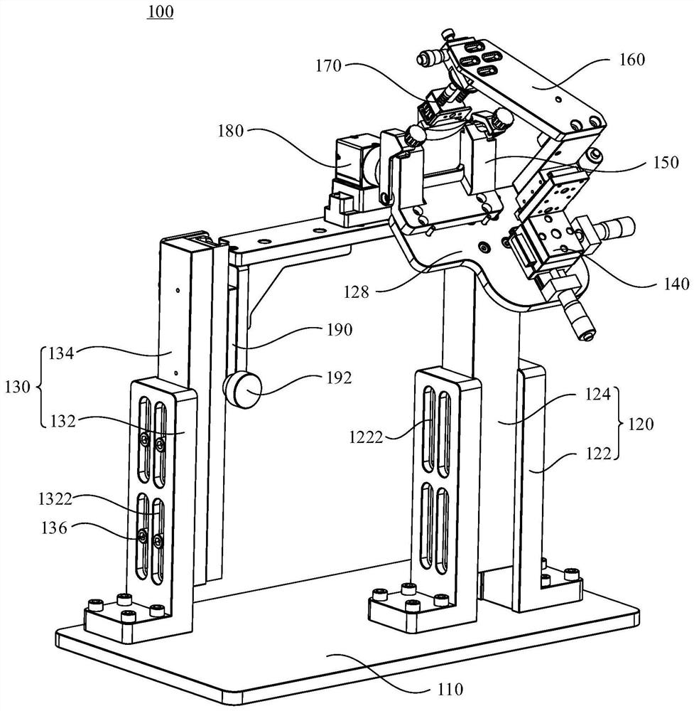
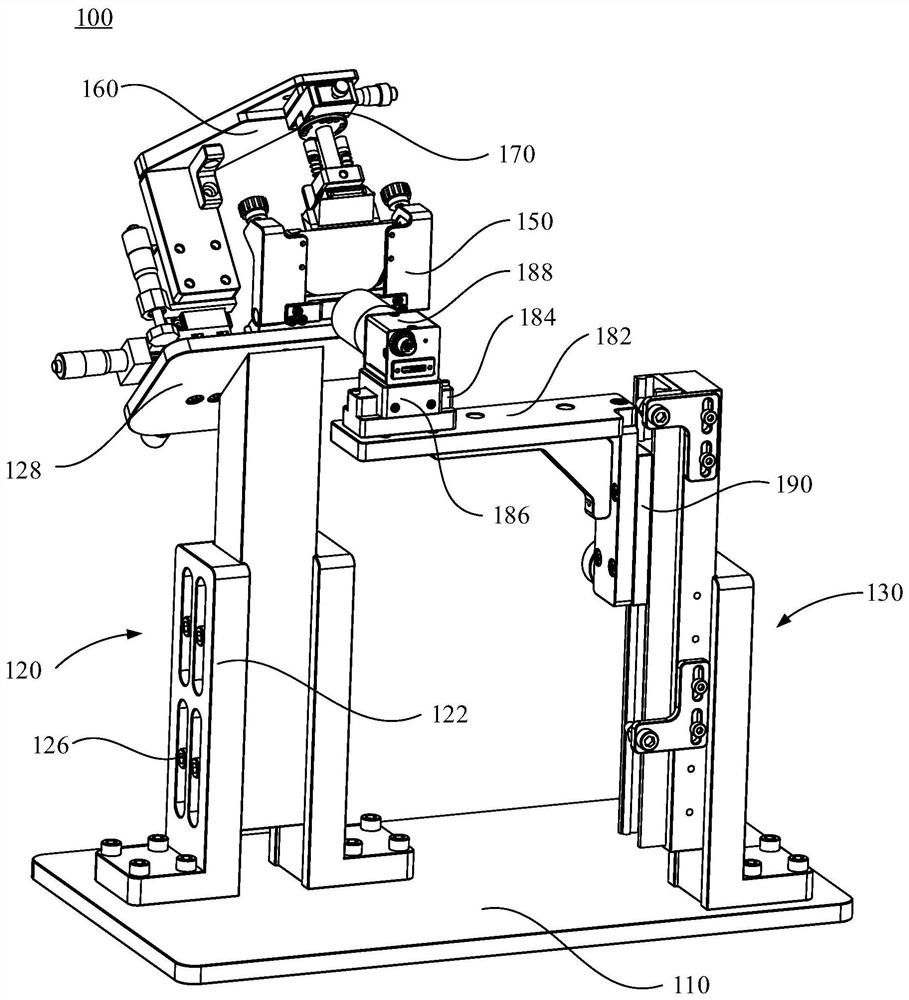
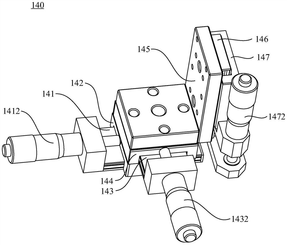
The invention discloses a calibration device of an optical waveguide display module, and relates to the technical field of assembly and manufacturing. The calibration device of the optical waveguide display module comprises a bottom plate, a first adjusting frame and a second adjusting frame, the first adjusting frame and the second adjusting frame are arranged on the bottom plate, a mounting plate is arranged on the first adjusting frame, a first adjusting assembly and a positioning assembly are arranged on the mounting plate, and the first adjusting assembly is connected with a second adjusting assembly through a connecting piece; the positioning assembly is used for fixing an optical assembly, the first adjusting assembly and the second adjusting assembly are used for jointly adjusting a display assembly so that the display assembly and the optical assembly can be matched to form the optical waveguide display module, and the second adjusting frame is provided with a detection assembly for detecting the calibration state between the optical assembly and the display assembly. The adjusting difficulty can be reduced, and the yield of products is improved.

Description

technical field [0001] The present application relates to the technical field of assembly and manufacturing, and in particular, to a calibration device for an optical waveguide display module. Background technique [0002] The optical display system of AR glasses is usually formed by a combination of various imaging systems and optical elements such as prisms, free-form surfaces, and optical waveguides. Imaging system, used to provide display content for the device. It can be a self-luminous active device, such as a light-emitting diode panel, or a liquid crystal display that requires external light source illumination, as well as digital micromirror arrays and laser beam scanners based on MEMS. [0003] When AR glasses use an optical waveguide as an optical element, after the imaging system completes the imaging process, the waveguide couples the light into the glass substrate, and transmits the light to the front of the eye through the principle of "total reflection" and ...

Claims


Application Information

Patent Timeline
IPC IPC(8): G02B27/62
CPCG02B27/62
Inventor 沈剑康江琪吴峰峄林思宇刘风雷
Owner ZHEJIANG CRYSTAL OPTECH
Learn More