Supercharge Your Innovation With Domain-Expert AI Agents!

Microphone

A microphone and substrate technology, applied in the field of microphones, can solve the problems of electromagnetic noise interference of microphones, large space occupied by shielding covers, and limited application scenarios, etc., and achieve the effects of improving performance, small size, and eliminating noise interference

Active Publication Date: 2021-07-30
WINGTECH COMM
View PDF14 Cites 0 Cited by
  • Summary
  • Abstract
  • Description
  • Claims
  • Application Information

AI Technical Summary

Problems solved by technology

In the process of designing these smart terminals, the microphone is usually placed in the antenna clearance area or in an area close to the antenna clearance area, but the electromagnetic waves generated by the antenna will radiate the microphone and cause electromagnetic noise interference to the microphone
[0003] In the prior art, in order to enhance the shielding effect on antenna radiation, a shielding cover is usually added around the microphone to interfere with the electromagnetic noise of the antenna. However, due to process limitations and other reasons, the shielding cover is not sealed, and there will be Narrow gaps, there are still some electromagnetic radiation that cannot be shielded, and the shielding cover set by the existing process takes up a lot of space, and the applicable scenarios are relatively limited

Method used


Image

  • Microphone
  • Microphone
  • Microphone

Examples


Embodiment Construction

[0030] In order to more clearly understand the above objects, features and advantages of the present disclosure, the solutions of the present disclosure will be further described below. It should be noted that, in the case of no conflict, the embodiments of the present disclosure and the features in the embodiments can be combined with each other.

[0031] In the following description, many specific details are set forth in order to fully understand the present disclosure, but the present disclosure can also be implemented in other ways than described here; obviously, the embodiments in the description are only some of the embodiments of the present disclosure, and Not all examples.

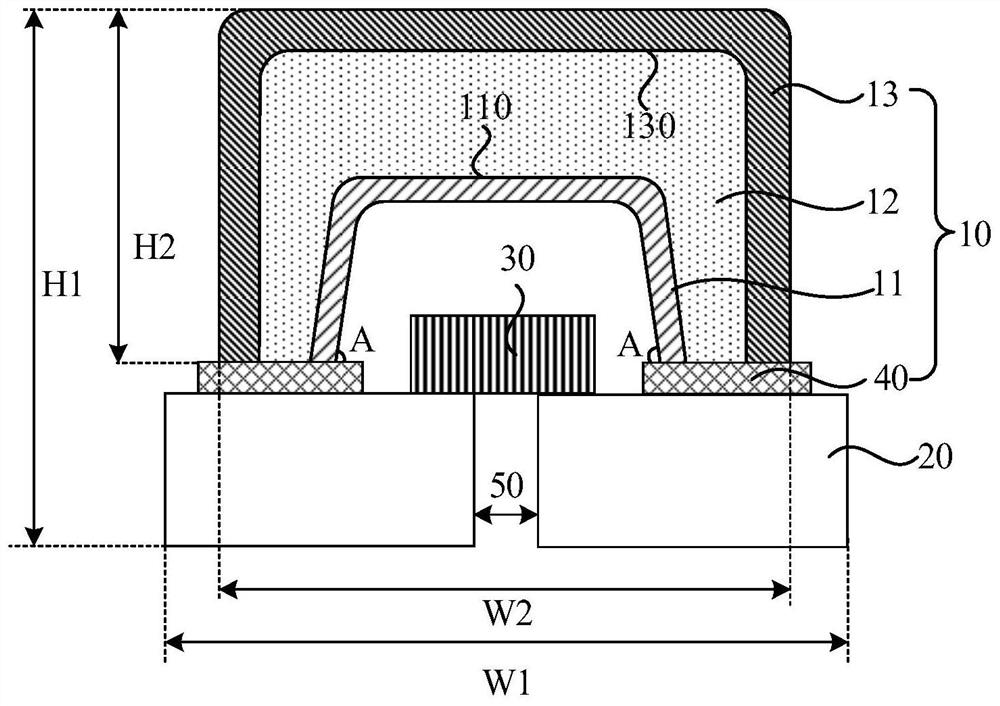
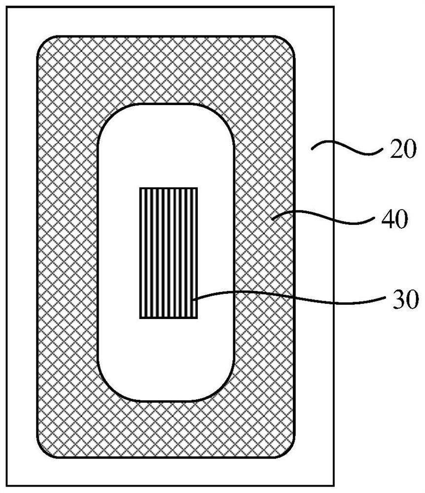
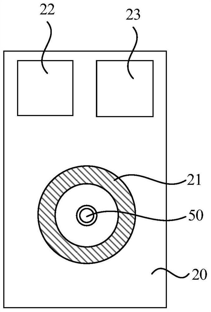
[0032] figure 1 It is a schematic diagram of a front view structure of a microphone provided by an embodiment of the present invention, figure 2 is a schematic top view structural diagram of a microphone provided by an embodiment of the present invention, image 3 It is a schematic diagram of...


PUM

PropertyMeasurementUnit
Thicknessaaaaaaaaaa
Withstand temperatureaaaaaaaaaa

Abstract

The invention relates to a microphone. The microphone comprises a shell, a substrate and an acoustoelectric sensor, wherein the shell comprises a first metal layer, an insulating layer and a second metal layer which are stacked in sequence; the shell is prepared by using a laser direct structuring technology; the shell further comprises a ground connecting part; the ground connecting part is located on the substrate and surrounds the acoustoelectric sensor in a closed mode; the first metal layer and the second metal layer are in electric contact with the ground connecting part; the shell is located on the substrate; a cavity is formed between the shell and the substrate; the acoustoelectric sensor is arranged in the cavity and on the substrate; and the acoustoelectric sensor is arranged corresponding to the sound hole penetrating through the substrate; The size of the microphone is smaller, and the performance of the microphone is improved.

Description

technical field [0001] The present disclosure relates to the technical field of microphones, in particular to a microphone. Background technique [0002] With the gradual development of artificial intelligence technology, more and more mobile terminals are suitable for microphones, such as mobile phones, tablets, robots, smart watches, etc. In the process of designing these smart terminals, the microphone is usually set in or close to the antenna clearance area, but the electromagnetic waves generated when the antenna is working will radiate the microphone and cause electromagnetic noise interference to the microphone. [0003] In the prior art, in order to enhance the shielding effect on antenna radiation, a shielding cover is usually added around the microphone to interfere with the electromagnetic noise of the antenna. However, due to process limitations and other reasons, the shielding cover is not sealed, and there will be There are still some electromagnetic radiation...

Claims


Application Information

Patent Timeline
IPC IPC(8): H04R1/08H04R31/00
CPCH04R1/08H04R31/00H04R2201/02
Inventor 吴伟浩
Owner WINGTECH COMM
Features
  • R&D
  • Intellectual Property
  • Life Sciences
  • Materials
  • Tech Scout
  • Unparalleled Data Quality
  • Higher Quality Content
  • 60% Fewer Hallucinations
Learn More