Posterior ankle bone fracture plate

A bone plate and distal technology, applied in the field of medical devices, can solve the problems of insufficient fixation strength, inability to fix comminuted fractures of the posterior malleolus, and no standard treatment plan.

Inactive Publication Date: 2021-08-03
SHANGHAI EAST HOSPITAL EAST HOSPITAL TONGJI UNIV SCHOOL OF MEDICINE
View PDF0 Cites 0 Cited by
  • Summary
  • Abstract
  • Description
  • Claims
  • Application Information

AI Technical Summary

Problems solved by technology

The fixation schemes for posterior malleolus fractures vary in clinical practice, and there is no standard treatment scheme. Currently, the 1/3 tubular plate, T-plate, posterior malleolus supporting plate and miniature locking plate cannot fix the posterio

Method used


Image

  • Posterior ankle bone fracture plate
  • Posterior ankle bone fracture plate
  • Posterior ankle bone fracture plate

Examples


Embodiment 1

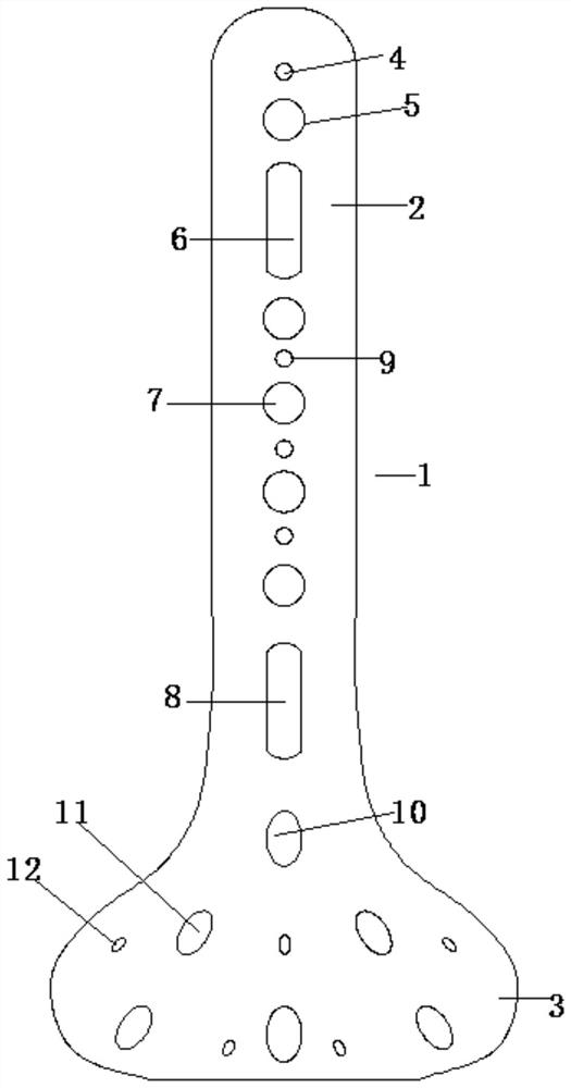
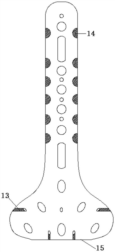
[0018] Such as Figure 1-Figure 3 A posterior malleolus bone plate is shown, comprising a bone plate body 1, the bone plate body 1 has a T-shaped structure as a whole, and the bone plate body 1 is divided into a proximal bone plate 2 and a distal bone plate 3. The distal bone plate 3 is an arc-shaped structure, extending curvedly to both sides. The proximal bone plate 2 and the distal bone plate 3 are smoothly transitioned and connected, forming an integrated structure. The middle part of the proximal bone plate 2 is from top to bottom. There are proximal Kirschner wire hole 4, proximal locking hole 5, sliding hole 6, proximal locking hole I7, and sliding hole I8 in sequence, and there are proximal Kirschner wire holes I9 between adjacent locking holes I7 , the proximal Kirschner wire hole 4 can be used for temporary fixation, and the sliding hole 6 is used for temporary pressurization and fixation of the proximal end of the bone plate through cortical bone screws, so that the...

Embodiment 2

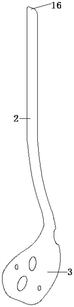
[0020] Such as Figure 1-Figure 3 A posterior ankle bone plate is shown, including a bone plate body 1, which is a T-shaped structure as a whole, and the edge of the bone plate body is a smooth curved surface structure, which reduces friction with soft tissue and reduces postoperative discomfort. , the bone plate body 1 is divided into a proximal bone plate 2 and a distal bone plate 3, the distal bone plate 3 is an arc-shaped structure extending to both sides, the proximal bone plate 2 and the distal bone plate The plates 3 are smoothly transitioned and connected, and have an integrated structure. The upper end surface of the proximal bone plate 2 is a bevel structure 16, which facilitates the insertion of the bone plate, facilitates the operation of the operator, and reduces soft tissue irritation. In the middle part, there are proximal Kirschner wire hole 4, proximal locking hole 5, sliding hole 6, proximal locking hole I7 and sliding hole I8 in order from top to bottom. Th...


PUM


Abstract

The invention discloses a posterior ankle bone fracture plate which comprises a bone fracture plate body; the bone fracture plate body is divided into a near-end bone fracture plate and a far-end bone fracture plate, the far-end bone fracture plate is of an arc-shaped structure and extends towards curves on the two sides, and the near-end bone fracture plate and the far-end bone fracture plate are in smooth transition connection; near-end kirschner wire holes, near-end locking holes, sliding holes, near-end locking holes I and sliding holes I are sequentially formed in the middle of the near-end bone fracture plate from top to bottom, the near-end kirschner wire holes I are formed between the adjacent near-end locking holes I; a far-end upper locking hole is formed in the middle of the upper end of the far-end bone fracture plate, and far-end locking holes are formed in the periphery of the far-end bone fracture plate; and a far-end kirschner wire hole is formed between every two adjacent far-end locking holes, and the locking hole angle of the far-end locking holes and the locking hole angle of the far-end upper locking hole are in the tangential direction of the highest point of the tibia far-end articular surface in the ankle joint. The far end of the bone fracture plate extends towards the curved surfaces on the two sides, six locking holes are relatively and uniformly distributed, and the bone fracture plate can be suitable for simple and complex posterior ankle fractures.

Description

technical field [0001] The invention relates to the technical field of medical devices, in particular to a posterior ankle bone plate. Background technique [0002] The fracture of the posterior lip of the tibia is a fracture of the posterior articular surface of the distal tibia, which is clinically known as the posterior malleolus fracture of the ankle joint. Most fractures of the posterior lip of the tibia are clinically caused by violent sprains of the ankle joint. For posterior malleolus fractures, a treatment plan should be formulated according to the size of the patient's fracture fragment. If the fracture fragment involves more than 1 / 3 of the articular surface of the distal tibia, the patient needs surgical treatment to immobilize the ankle joint in time to avoid dislocation of the ankle joint. The fixation schemes for posterior malleolus fractures vary in clinical practice, and there is no standard treatment scheme. The currently used 1 / 3 tubular plate, T-plate, ...

Claims


Application Information

Patent Timeline
IPC IPC(8): A61B17/80
CPCA61B17/8061A61B17/808
Inventor 刘立峰高硕彭青武乐方楠
Owner SHANGHAI EAST HOSPITAL EAST HOSPITAL TONGJI UNIV SCHOOL OF MEDICINE
Why Eureka
Try Eureka