Pointing process and device beneficial to drawing and die penetrating of steel wire

A steel wire and rolling tip technology, applied in the field of steel wire drawing and piercing, can solve the problems of low production efficiency, long rolling time, increased rolling burrs, etc., and achieve the effects of high work efficiency, fast heating speed and simple operation.

Pending Publication Date: 2021-08-03
中钢集团郑州金属制品研究院股份有限公司 +2
7 Cites 1 Cited by

AI-Extracted Technical Summary

Problems solved by technology

At present, the commonly used pointing machine adopts the method of mechanical rolling for pointing. The mechanical pointing has the following disadvantages: 1. The rolling time is long; 2. The steel wire needs to be rotated. It is very hard, and ...

Abstract

The invention discloses a pointing process and device beneficial to drawing and die penetrating of a steel wire, and belongs to the technical field of drawing and die penetrating of steel wires in deep processing of wire rods. The pointing device comprises a rotary straightener, a fixed chuck, an electromagnetic induction heating pipe and a movable chuck which are sequentially arranged in the direction of the steel wire. The pointing process comprises the following steps of paying off and straightening, pressing the steel wire, heating the steel wire, breaking the steel wire, and drawing die penetrating. According to the pointing process and device beneficial to drawing and die penetrating of the steel wire, the steel wire is heated through the electromagnetic induction effect, the heating speed is high, and cleanliness and no pollution are achieved; the strength of the steel wire is greatly reduced after the steel wire is heated, when the end of the steel wire moves forwards at a low speed along a sliding rail along with the movable chuck driven by a lead screw, the heated steel wire can be evenly thinned and snapped only by means of small clamping force, and a steel wire conical head beneficial to drawing and die penetrating of the steel wire is rapidly, safely and stably formed; and the accidents of hurting people, hurting fingers, squeezing and the like due to the fact that a pointing machine is manually used for mechanical pointing are avoided, operation is easy, time is shortened and labor is saved, working efficiency is high, operation is stable, and use is safe.

Application Domain

Drawing dies

Technology Topic

Wire rodMachine

Image

  • Pointing process and device beneficial to drawing and die penetrating of steel wire
  • Pointing process and device beneficial to drawing and die penetrating of steel wire
  • Pointing process and device beneficial to drawing and die penetrating of steel wire

Examples

  • Experimental program(3)

Example Embodiment

[0024] Embodiment one
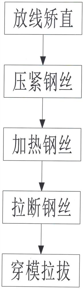
[0025] A kind of sharpening process that is beneficial to steel wire drawing and piercing die in embodiment one is made up of following steps:
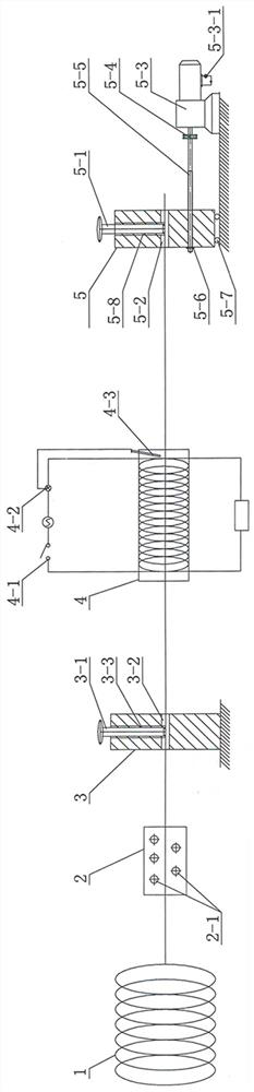
[0026] A. Pay-off and straightening: Unfold a wire rod with a diameter of 15.5mm for pay-off. The unrolled steel wire 1 runs horizontally and horizontally between the upper and lower rows of straightening rollers 2-1 of the rotary straightener 2. During the process, the steel wire 1 is corrected into a straight strip (to facilitate subsequent threading);
[0027] B. Press the steel wire: the straightened steel wire 1 passes through the threading hole Ⅰ3-2 in the fixed chuck 3, the inner cavity of the electromagnetic induction heating tube 4 with a length of 800mm, and the wire hole Ⅱ5 in the moving chuck 5 -2, turn off the rotary straightener 2 at this time; then screw down the pressing bolt Ⅰ3-1 in the fixed chuck 3 and the pressing bolt Ⅱ5-1 in the moving chuck 5 respectively, so that the pressing bolt Ⅰ3- 1 and the lower end of the wire-pressing bolt Ⅱ5-1 contact and press the upper surface of the steel wire 1 (realize the front-end and rear-end fixation of the heated section steel wire 1, in preparation for the subsequent breaking of the steel wire), and ensure that the wire-pressing bolt The distance between Ⅰ3-1 and pressing bolt Ⅱ5-1 is 2 to 3 times the length of the electromagnetic induction heating tube 4;
[0028] C. Heating steel wire: open and select the frequency specification corresponding to the required frequency in the induction frequency gear regulator 4-2, control the timing heating switch 4-1 to start, and the electromagnetic induction heating tube 4 generates an alternating magnetic field after being powered on, and utilizes electromagnetic induction The effect rapidly heats the steel wire 1 located in the inner cavity of the electromagnetic induction heating tube 4; when the electric couple 4-3 detects that the steel wire 1 is heated to 980°C, the electric couple 4-3 feeds back the temperature signal to the induction frequency gear regulator 4-2, control the timing heating switch 4-1 to disconnect and stop heating;
[0029] D. Breaking the steel wire: the strength of the heated steel wire is reduced to 1/4 of the normal strength; turn on the forward and reverse conversion switch 5-3-1 of the gear motor 5-3 to the forward gear, and pass through the coupling 5-4 Drive the lead screw 5-5 to rotate forward, and then through the cooperation of the lead screw 5-5 and the threaded hole 5-6 of the lead screw, the movable chuck 5 is moved forward at a speed of 3mm/s, and the rear end is pressed by the fixed chuck 3 Tightly fixed, the front end is pressed and fixed by the moving chuck 5, and the steel wire 1 that moves slowly forward together with the moving chuck 5 is gradually thinned evenly until disconnected, and the forward and reverse conversion switch 5-3-1 is turned off to make the gear motor 5 -3 stop the rotation, and at this time, a steel tap head that is beneficial to the drawing and passing of the steel wire is formed at the fracture of the steel wire 1;
[0030] E. Die-threading and drawing: Unscrew the thread-pressing bolt Ⅰ3-1 and thread-pressing bolt Ⅱ5-1 upwards and backwards respectively, and loosen the fixation of both ends of the fracture of the steel wire 1; After the threading hole Ⅰ3-2 of the wire rod and the rotary straightener 2 are removed, the wire drawing die 6 is used for subsequent die drawing, that is, the cone fracture of the steel wire 1 at the connected end of the wire rod penetrates the wire drawing die 6 and is embedded in the die sleeve 6-1 The mold core 6-2 of the inner cavity starts drawing after the tapered inner hole; and the steel wire 1 at the other end of the fracture is recycled as a waste product; at the same time, the forward and reverse conversion switch 5-3-1 of the gear motor 5-3 is turned on to reverse. Turn gear position, reduction motor 5-3 reverses, drives lead screw 5-5 reverse rotation, and moving collet 5 retreats and resets, and gets ready for the next pointing operation.

Example Embodiment

[0031] Embodiment two
[0032] A kind of sharpening process that is beneficial to steel wire drawing and piercing die among the embodiment two is made up of following steps:
[0033] A. Pay-off and straightening: Unfold the wire rod with a diameter of 5.5mm for pay-off, and the unrolled steel wire 1 runs horizontally and horizontally between the upper and lower rows of straightening rollers 2-1 of the rotary straightener 2. During the process, the steel wire 1 is corrected into a straight strip (to facilitate subsequent threading);
[0034] B. Press the steel wire: the straightened steel wire 1 passes through the threading hole Ⅰ3-2 in the fixed chuck 3, the inner cavity of the electromagnetic induction heating tube 4 with a length of 300mm, and the wire hole Ⅱ5 in the moving chuck 5 -2, turn off the rotary straightener 2 at this time; then screw down the pressing bolt Ⅰ3-1 in the fixed chuck 3 and the pressing bolt Ⅱ5-1 in the moving chuck 5 respectively, so that the pressing bolt Ⅰ3- 1 and the lower end of the wire-pressing bolt Ⅱ5-1 contact and press the upper surface of the steel wire 1 (realize the front-end and rear-end fixation of the heated section steel wire 1, in preparation for the subsequent breaking of the steel wire), and ensure that the wire-pressing bolt The distance between Ⅰ3-1 and pressing bolt Ⅱ5-1 is 2 to 3 times the length of the electromagnetic induction heating tube 4;
[0035] C. Heating steel wire: open and select the frequency specification corresponding to the required frequency in the induction frequency gear regulator 4-2, control the timing heating switch 4-1 to start, and the electromagnetic induction heating tube 4 generates an alternating magnetic field after being powered on, and utilizes electromagnetic induction The effect rapidly heats the steel wire 1 located in the inner cavity of the electromagnetic induction heating tube 4; when the electric couple 4-3 detects that the steel wire 1 is heated to 890°C, the electric couple 4-3 feeds back the temperature signal to the induction frequency gear regulator 4-2, control the timing heating switch 4-1 to disconnect and stop heating;
[0036] D. Breaking the steel wire: the strength of the heated steel wire is reduced to 1/2 of the normal strength; turn on the forward and reverse conversion switch 5-3-1 of the gear motor 5-3 to the forward gear, and pass through the coupling 5-4 Drive the lead screw 5-5 to rotate forward, and then through the cooperation of the lead screw 5-5 and the threaded hole 5-6 of the lead screw, the movable chuck 5 is moved forward at a speed of 8 mm/s, and the rear end is pressed by the fixed chuck 3 Tightly fixed, the front end is pressed and fixed by the moving chuck 5, and the steel wire 1 that moves slowly forward together with the moving chuck 5 is gradually thinned evenly until disconnected, and the forward and reverse conversion switch 5-3-1 is turned off to make the gear motor 5 -3 stop the rotation, and at this time, a steel tap head that is beneficial to the drawing and passing of the steel wire is formed at the fracture of the steel wire 1;
[0037] E. Die-threading and drawing: Unscrew the thread-pressing bolt Ⅰ3-1 and thread-pressing bolt Ⅱ5-1 upwards and backwards respectively, and loosen the fixation of both ends of the fracture of the steel wire 1; After the threading hole Ⅰ3-2 of the wire rod and the rotary straightener 2 are removed, the wire drawing die 6 is used for subsequent die drawing, that is, the cone fracture of the steel wire 1 at the connected end of the wire rod penetrates the wire drawing die 6 and is embedded in the die sleeve 6-1 The mold core 6-2 of the inner cavity starts drawing after the tapered inner hole; and the steel wire 1 at the other end of the fracture is recycled as a waste product; at the same time, the forward and reverse conversion switch 5-3-1 of the gear motor 5-3 is turned on to reverse. Turn gear position, reduction motor 5-3 reverses, drives lead screw 5-5 reverse rotation, and moving collet 5 retreats and resets, and gets ready for the next pointing operation.

Example Embodiment

[0038] Embodiment Three
[0039] A kind of sharpening process that is beneficial to steel wire drawing and piercing die among the embodiment three is made up of following steps:
[0040] A. Pay-off and straightening: Unfold a wire rod with a diameter of 10.5mm for pay-off, and the unrolled steel wire 1 runs horizontally and horizontally between the upper and lower rows of straightening rollers 2-1 of the rotary straightener 2, During the process, the steel wire 1 is corrected into a straight strip (to facilitate subsequent threading);
[0041] B. Press the steel wire: the straightened steel wire 1 passes through the threading hole Ⅰ3-2 in the fixed chuck 3, the inner cavity of the electromagnetic induction heating tube 4 with a length of 600mm, and the wire hole Ⅱ5 in the moving chuck 5 -2, turn off the rotary straightener 2 at this time; then screw down the pressing bolt Ⅰ3-1 in the fixed chuck 3 and the pressing bolt Ⅱ5-1 in the moving chuck 5 respectively, so that the pressing bolt Ⅰ3- 1 and the lower end of the wire-pressing bolt Ⅱ5-1 contact and press the upper surface of the steel wire 1 (realize the front-end and rear-end fixation of the heated section steel wire 1, in preparation for the subsequent breaking of the steel wire), and ensure that the wire-pressing bolt The distance between Ⅰ3-1 and pressing bolt Ⅱ5-1 is 2 to 3 times the length of the electromagnetic induction heating tube 4;
[0042] C. Heating steel wire: open and select the frequency specification corresponding to the required frequency in the induction frequency gear regulator 4-2, control the timing heating switch 4-1 to start, and the electromagnetic induction heating tube 4 generates an alternating magnetic field after being powered on, and utilizes electromagnetic induction The effect quickly heats the steel wire 1 located in the inner cavity of the electromagnetic induction heating tube 4; when the electric couple 4-3 detects that the steel wire 1 is heated to 920°C, the electric couple 4-3 feeds back the temperature signal to the induction frequency gear regulator 4-2, control the timing heating switch 4-1 to disconnect and stop heating;
[0043] D. Breaking the steel wire: the strength of the heated steel wire is reduced to 2/5 of the normal strength; turn on the forward and reverse conversion switch 5-3-1 of the gear motor 5-3 to the forward gear, and pass through the coupling 5-4 Drive the lead screw 5-5 to rotate forward, and then through the cooperation of the lead screw 5-5 and the threaded hole 5-6 of the lead screw, the movable chuck 5 is moved forward at a speed of 5mm/s, and the rear end is pressed by the fixed chuck 3 Tightly fixed, the front end is pressed and fixed by the moving chuck 5, and the steel wire 1 that moves slowly forward together with the moving chuck 5 is gradually thinned evenly until disconnected, and the forward and reverse conversion switch 5-3-1 is turned off to make the gear motor 5 -3 stop the rotation, and at this time, a steel tap head that is beneficial to the drawing and passing of the steel wire is formed at the fracture of the steel wire 1;
[0044] E. Die-threading and drawing: Unscrew the thread-pressing bolt Ⅰ3-1 and thread-pressing bolt Ⅱ5-1 upwards and backwards respectively, and loosen the fixation of both ends of the fracture of the steel wire 1; After the threading hole Ⅰ3-2 of the wire rod and the rotary straightener 2 are removed, the wire drawing die 6 is used for subsequent die drawing, that is, the cone fracture of the steel wire 1 at the connected end of the wire rod penetrates the wire drawing die 6 and is embedded in the die sleeve 6-1 The mold core 6-2 of the inner cavity starts drawing after the tapered inner hole; and the steel wire 1 at the other end of the fracture is recycled as a waste product; at the same time, the forward and reverse conversion switch 5-3-1 of the gear motor 5-3 is turned on to reverse. Turn gear position, reduction motor 5-3 reverses, drives lead screw 5-5 reverse rotation, and moving collet 5 retreats and resets, and gets ready for the next pointing operation.

PUM

PropertyMeasurementUnit
Diameter5.5 ~ 18.0mm
tensileMPa
Particle sizePa
strength10

Description & Claims & Application Information

We can also present the details of the Description, Claims and Application information to help users get a comprehensive understanding of the technical details of the patent, such as background art, summary of invention, brief description of drawings, description of embodiments, and other original content. On the other hand, users can also determine the specific scope of protection of the technology through the list of claims; as well as understand the changes in the life cycle of the technology with the presentation of the patent timeline. Login to view more.

Similar technology patents

Classification and recommendation of technical efficacy words

  • Fast heating
  • Reduce intensity

System comprising duel-fuel and after treatment for heavy-heavy duty diesel (HHDD) engines

ActiveUS10287943B1Eliminating of time lapseFast heatingInternal combustion piston enginesFuel supply apparatusDecreased carbon dioxideExhaust emission
Owner:CLEAN POWER TECH LLC

Dimming mirror with blind zone sub-mirror and indicator

ActiveUS6919796B2Reduce light intensityReduce intensityMirrorsAnti-collision systemsComputer visionWing mirror
Owner:MAGNA MIRRORS OF AMERICA
Why Eureka
Try Eureka