A dry gas seal structure with controllable end face stiffness

A dry gas sealing and controllable technology, applied in the direction of engine sealing, mechanical equipment, engine components, etc., can solve the problems of insufficient use effect, weak adaptive ability, etc., to prevent friction, improve sealing effect, enhance The effect of adaptive capacity

Active Publication Date: 2022-02-11
LANZHOU UNIVERSITY OF TECHNOLOGY
View PDF3 Cites 0 Cited by
  • Summary
  • Abstract
  • Description
  • Claims
  • Application Information

AI Technical Summary

Problems solved by technology

[0004] The invention provides a dry gas seal structure with controllable end surface stiffness to solve the problems of weak self-adaptability and insufficient use effect in high-parameter service environments of rigid dry-gas seal technology in the prior art, and to realize improvement in high-parameter service The sealing effect in the environment and the purpose of the dynamic stability of the shaft system

Method used


Image

  • A dry gas seal structure with controllable end face stiffness
  • A dry gas seal structure with controllable end face stiffness
  • A dry gas seal structure with controllable end face stiffness

Examples


Embodiment 1

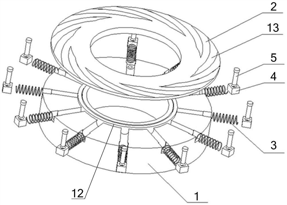
[0037] Such as figure 1 and figure 2 A dry gas seal structure with controllable end face stiffness is shown, including a moving ring and a static ring, the moving ring is a rigid end face, the static ring includes a static ring body 1, and the end face of the static ring body 1 is embedded with several The annular uniformly distributed elastic member 3 also includes an annular flat foil 2 assembled on the end surface of the static ring body 1, the flat foil 2 is in contact with the elastic member 3, and a dynamic pressure groove is opened on the surface of the flat foil 2 13.

[0038] In this embodiment, the inner diameter side of the end surface of the static ring body 1 is provided with an annular protrusion 12 to form a high surface of the ring, and the outer diameter side of the end surface of the static ring body 1 automatically forms a lower surface of the ring; the inner diameter side of the flat foil 2 is assembled on the said On the annular protrusion 12.

[0039]...

Embodiment 2

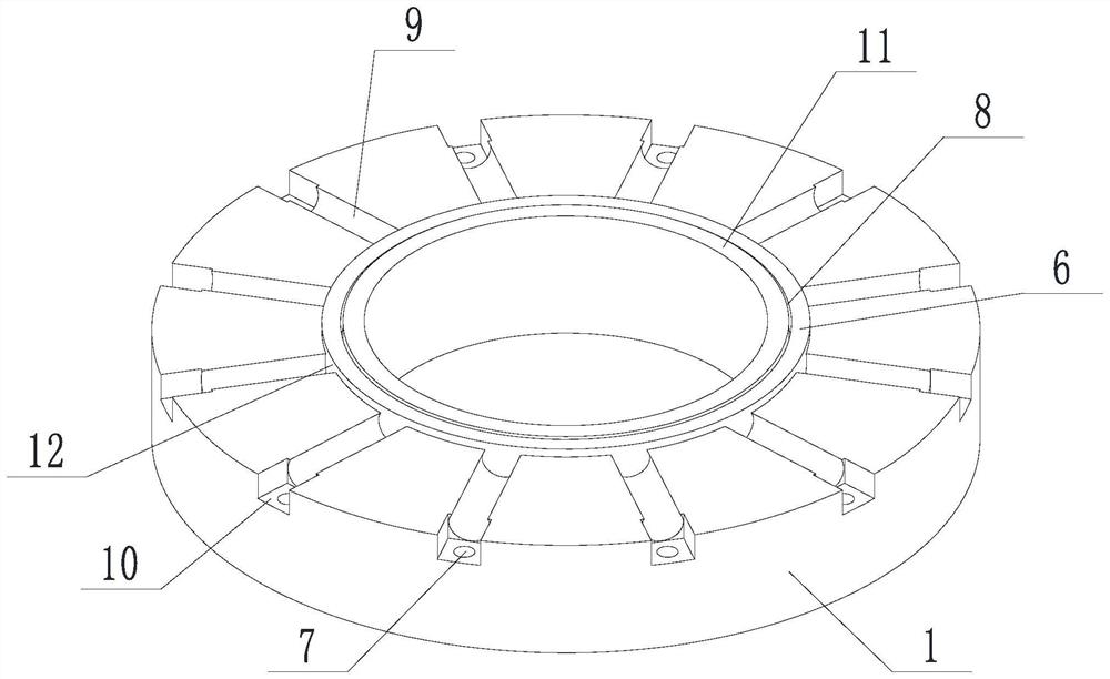
[0046] Such as Figure 1 to Figure 7 In the shown dry gas seal structure with controllable end face stiffness, on the basis of Embodiment 1, an annular groove 8 is arranged on the annular protrusion 12, and the inner diameter side of the flat foil 2 is arranged in contact with the annular groove 8, the first extension part 201 is matched with the first extension part 201, and the first extension part 201 is held in the annular groove 8 by clearance fit. A second extension 202 is provided on the outer diameter side of the flat foil 2 , and the extension length of the second extension 202 in the axial direction is smaller than the minimum height of the annular protrusion 12 .

[0047] In this embodiment, the annular groove 8 divides the annular protrusion 12 into a seal dam 11 near the inner diameter end and a support dam 6 near the outer diameter end; the height of the seal dam 11 is greater than the height of the support dam 6, and the seal dam 11 and the support The height d...

Embodiment 3

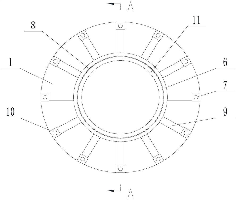
[0052] A dry gas seal structure with controllable end face stiffness, on the basis of any of the above-mentioned embodiments, such as Figure 1 to Figure 11 As shown, the end surface of the static ring body 1 is provided with a plurality of annular evenly distributed arc-shaped grooves 9 , and the axes of the arc-shaped grooves 9 are distributed along the radial direction of the static ring body 1 . The elastic part 3 is clearance fit in the arc groove 9, and the elastic part 3 is partially exposed to the plane where the end face of the static ring body 1 is located; in this embodiment, the elastic part 3 is partially exposed along the axial direction of the static ring body 1, which ensures the Effective contact of the flat foil 2.

[0053] Such as Figure 9 As shown, the arc groove 9 is an arc groove with a central angle greater than 180°, that is Figure 9 α is less than 180°.

[0054] In the present embodiment, the elastic member 3 is as Figure 8 Compressible spring s...


PUM


Abstract

The invention discloses a dry gas sealing structure with controllable end face stiffness, which includes a moving ring and a static ring, the moving ring is a rigid end face, the static ring includes a static ring body, and a plurality of annular rings are embedded in the end face of the static ring body The evenly distributed elastic member also includes an annular flat foil assembled on the end surface of the static ring body, the flat foil is in contact with the elastic member, and a dynamic pressure groove is opened on the surface of the flat foil. The invention provides a dry gas seal structure with controllable end surface stiffness to solve the problems of weak self-adaptability and insufficient use effect in high-parameter service environments of rigid dry-gas seal technology in the prior art, and to realize improvement in high-parameter service The sealing effect in the environment and the purpose of the dynamic stability of the shafting.

Description

technical field [0001] The invention relates to the field of dry gas sealing, in particular to a dry gas sealing structure with controllable end surface stiffness. Background technique [0002] The sealing device for aviation shaft end can effectively play the role of oil and gas isolation in the cavity, return flow and leakage control, but because most of the combustion chamber is high-temperature gas, the rotor rotates at high speed under the action of unstable air flow, and the high-altitude behavior is complex and changeable. Noise excitation and impact are random, therefore, key sealing parts are prone to deformation such as creep and fatigue under the extreme coupling environment effect of aerodynamic thermodynamic sound. At the same time, the rigid dry gas seal structure used in the prior art is mostly made of tungsten carbide, silicon carbide and other materials, and its anti-interference ability is poor, and the problem of friction and wear on the end face is very e...

Claims


Application Information

Patent Timeline
Patent Type & Authority Patents(China)
IPC IPC(8): F16J15/40
CPCF16J15/40
Inventor 徐洁蒋海涛严如奇俞树荣杨小成王世鹏丁俊华丁雪兴
Owner LANZHOU UNIVERSITY OF TECHNOLOGY
Why Eureka
Try Eureka