A pressure transmitter with overpressure protection

A transmitter and pressure technology, applied in the direction of measuring fluid pressure, instruments, measuring devices, etc., can solve the problems of poor overpressure protection effect and achieve high accuracy

Active Publication Date: 2021-09-07
胜利油田东强机电设备制造有限公司
View PDF1 Cites 0 Cited by
  • Summary
  • Abstract
  • Description
  • Claims
  • Application Information

AI Technical Summary

Problems solved by technology

[0006] The purpose of the present invention is to propose a pressure transmitter with overpressure protection in order to solve the problem of poor overpressure protection effect of existing pressure transmitters

Method used


Image

  • A pressure transmitter with overpressure protection
  • A pressure transmitter with overpressure protection
  • A pressure transmitter with overpressure protection

Examples


Embodiment 1

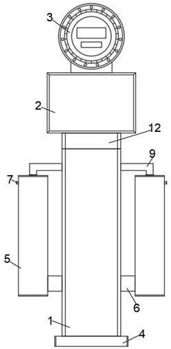
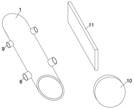
[0051] See Figure 1-3 As shown, a pressure transmitter having overpressive protection, including the inverting chamber 1, the conversion chamber 2, and the display 3, and the pressure input port 4 is provided at the bottom of the press cavity 1, and the inner diameter of the pressure input port 4 is larger than the induced cavity. The inner diameter of 1, the pressure fluid enters the inside of the pressing chamber 1 through the pressure input port 4, and both sides of the press cavity 1 are provided with the buffer chamber 5, the buffer cavity 5 is close to one end of the pressure input port 4 and the inside of the inverting chamber 1. The wall is fixedly connected to the input conduit 6, and the input conduit 6 is provided with an electromagnetic valve, and the solenoid valve of the input conduit 6 is used to truncate the input pipe 6 in the case of overpressure and the pressure relief, and the fluid is further entered by input pipe 6. When the buffer cavity 5 is inside, while t...

Embodiment 2

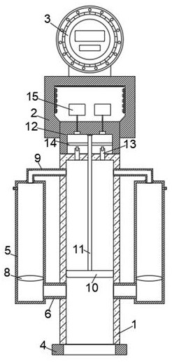
[0057] Please participate figure 2 As shown, the front surface of the display 3 is provided with a processor, and the processor communication is connected to an overpressure analysis module, the monitoring module, the storage module, and the controller are used to control the solenoid valve of the input conduit 6 and the solenoid valve of the pressure relief conduit 7. The opening and closing, switching the pressure and detection mode by inputting the pipe 6 and the solenoid valve of the pressure relief pipe 7, the overpressure analysis module is used to perform pressure overload analysis of the two buffer cavities 5, and the operation monitoring module is used to devices. The operation status is detected, and the storage module is used to store the running data of the device;

[0058] The process of pressure overload analysis of the overpressure analysis module to the buffer cavity 5 includes the following steps:

[0059] Step S1: After inputting the pressure fluid over the press...

Embodiment 3

[0071] See Figure 5 As shown in, for example, in Example 1 of the present embodiment is distinguished in that the side surface of the baffle 10 into the pressure chamber and the active side wall 1 is connected, and an electromagnetic snap between an inner sidewall of the baffle 10 into the top edge of the pressure chamber , the inner surface of the top wall 11 and the isolation diaphragm chamber 12 is fixedly connected to the bottom surface of the spacer 11 defines a slot 16, the top wall 16 is fixed into the slot with a spring 17 mounted evenly distributed, uniform distribution of the bottom of the spring 17 of the fixedly mounted between the pressure relief block 18, block 18 extends to the bottom of the relief slot 16 and the outer surface of the embedded baffle 10 mounted on the top of the pressure relief block 18 are connected to the front and rear sides of the inner sidewall into the pressure chamber 1 activity is provided with a gasket 18 between the block surface and the r...


PUM


Abstract

The invention relates to the technical field of pressure transmitters, and is used to solve the problem of poor overpressure protection effect of existing pressure transmitters, specifically a pressure transmitter with overpressure protection, including an inlet pressure chamber, a conversion There is a pressure input port at the bottom of the inlet pressure chamber, buffer chambers are arranged on both sides of the inlet pressure chamber, an input pipeline is fixedly connected between one end of the buffer chamber and the inner side wall of the inlet pressure chamber, and the other end of the buffer chamber is connected to the inner side wall of the inlet pressure chamber. A connecting pipe is arranged between the inner walls of the pressure chamber, a pressure relief pipe is fixedly connected to the inner wall of the buffer chamber away from the pressure inlet chamber, and a buffer diaphragm is arranged between the inner walls of the buffer chamber; the present invention provides a buffer diaphragm in the buffer chamber As well as compressible fluid, it can prevent the pressure fluid from continuously entering the pressure chamber until the pressure exceeds the threshold before overpressure protection is performed, causing damage to the pressure sensor.

Description

Technical field [0001] The present invention relates to a pressure transmitter technical field, in particular having a pressure transmitter overpressure protection. Background technique [0002] Refers oil exploration for oil excavation of oil stored in place, the extraction behavior, during the exploitation of oil and gas flows from the reservoir bottom and from bottom to increase the driving mode wellhead; oil in the national economy oil is important role in energy, compared with coal, having high energy density, easy storage and transportation, to a lesser extent post-combustion pollution of the atmosphere, etc; [0003] Pressure transmitter is indispensable signal detecting transmission device during oil production, an existing pressure transmitter used in oil exploration is generally not having over-pressure protection function, the pressure sensor is used in case of prolonged high pressure overloading It will seriously affect their life; [0004] Patent Gazette No. CN107209...

Claims


Application Information

Patent Timeline
Patent Type & Authority Patents(China)
IPC IPC(8): G01L19/06G01L19/00
CPCG01L19/0007G01L19/0618
Inventor 于涛孟繁宇刘新伟刘建军高京伟庄浩张伟伟王正杰宋晓鹏韩雷
Owner 胜利油田东强机电设备制造有限公司
Why Eureka
Try Eureka