Tool turret and rotating power head thereof

A technology of rotating power head and turret, applied in driving devices, manufacturing tools, metal processing mechanical parts, etc., can solve problems such as inconvenience, and achieve the effect of reducing torque and simplifying transmission structure

Active Publication Date: 2021-08-06
玉环图远机电有限公司
View PDF11 Cites 0 Cited by
  • Summary
  • Abstract
  • Description
  • Claims
  • Application Information

AI Technical Summary

Problems solved by technology

[0004] However, during the use of the above-mentioned CNC turret, the position between the cutter and the cutter head is relatively fixed, that is, the angle of the cutter can only be adjusted by adjusting the angle of the cutter head, which is inconvenient when processing complex workpieces.

Method used


Image

  • Tool turret and rotating power head thereof
  • Tool turret and rotating power head thereof
  • Tool turret and rotating power head thereof

Examples


Embodiment 1

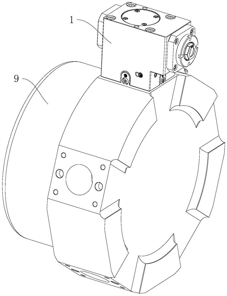
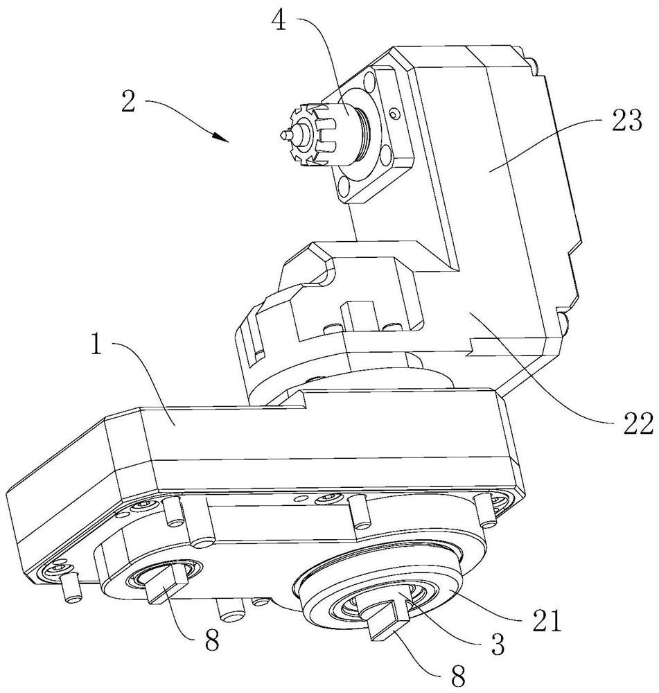
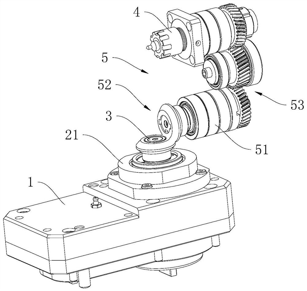
[0047] refer to figure 2 , 3 , a rotary power head, including a tool holder 1, a tool holder 2, a drive input shaft 3, a drive output shaft 4 and a drive transmission assembly 5. The knife holder 1 is fixedly connected to the cutter head 9 , the knife holder 2 is arranged on the knife holder 1 , and the drive input shaft 3 , the drive output shaft 4 and the drive transmission assembly 5 are all connected to the knife holder 2 .

[0048] The knife holder 2 includes a cylinder body 21 , a connecting portion 22 and a mounting portion 23 . The cylinder body 21 is embedded into the knife seat 1 , and at least one end of the cylinder body 21 extends out of the knife seat 1 . In this embodiment, both axial ends of the barrel 21 protrude from the tool holder 1 .

[0049] The drive input shaft 3 is coaxially rotatably connected in the cylinder body 21 through bearings, and both ends of the drive input shaft 3 extend out of the cylinder body 21 . The connecting portion 22 is fixedl...

Embodiment 2

[0059] refer to Figure 5 , 6 , the difference between this embodiment and embodiment 1 is that

[0060] The installation portion 23 includes a main body 231 and an end cover 232 ; and the end cover 232 defines an installation hole 233 for installing the drive output shaft 4 .

[0061] The drive output shaft 4 includes a coaxial shaft body 31 and a retaining ring 32 . One end of the shaft body 31 passes through the installation hole 233 and extends into the main body 231, and is connected to the main body 231 through bearing rotation; and one end of the shaft body 31 extending into the installation part 23 is connected to the drive transmission assembly 5; the other end of the shaft body 31 extends out The mounting part 23 is used for connecting the tool. The retaining ring 32 is disposed on the outer periphery of the shaft body 31 , and the end surface of the retaining ring 32 is slidably attached to the surface of the end cover 232 facing away from the main body 231 .

...


PUM


Abstract

The invention relates to a tool turret and a rotating power head thereof. The rotating power head comprises a tool apron, a tool rest, an adjusting input shaft, an adjusting transmission assembly, a driving input shaft, a driving output shaft and a driving transmission assembly; the tool apron is fixedly connected to a cutterhead; the tool rest is rotationally connected with the tool apron; the adjusting input shaft is rotationally connected with the tool apron; the adjusting transmission assembly is used for transmitting the rotating motion of the adjusting input shaft to the tool rest; the driving output shaft is rotationally connected with the tool rest; the rotating axis of the driving output shaft and the rotating axis of the tool rest are not parallel and not coincident; the driving transmission assembly is used for transmitting the rotating motion of the driving adjusting input shaft to the driving output shaft. The rotating power head is mounted on the cutterhead, in the workpiece machining process, the driving input shaft receives power and drives a tool to rotate, and cutting machining of the tool on the workpiece is achieved; if necessary, the adjusting input shaft receives power so as to drive the tool rest to deflect by a certain angle, and then the position and the angle of the tool connected to the tool rest are adjusted so as to complete machining of the complex workpiece.

Description

technical field [0001] The application relates to the field of numerically controlled turrets, in particular to a turret and its rotary power head. Background technique [0002] CNC turret is an important machine tool accessory, which can automatically switch tools according to the program to realize the machining of inner and outer cylindrical surfaces, inner and outer conical surfaces, grooving and drilling of workpieces. [0003] refer to figure 1 , the CNC turret includes a cutter head and a cutter seat, and a plurality of tool seats can be installed at intervals around the circumference of the cutter head. The knife seat is used for tool installation, and the knife disc and the knife seat are provided with a transmission assembly for transmitting torque from the motor to the tool. [0004] However, during the use of the above-mentioned CNC turret, the position between the tool and the cutter head is relatively fixed, that is, the angle of the cutter can only be adjust...

Claims


Application Information

Patent Timeline
IPC IPC(8): B23Q5/04B23Q1/25B23Q3/12
CPCB23Q5/04B23Q1/25B23Q3/12
Inventor 盛建强罗遇凡盛功涵
Owner 玉环图远机电有限公司
Why Eureka
Try Eureka