Brake pad grinding equipment for new energy automobile manufacturing

A technology for new energy vehicles and brake pads, which is applied in the direction of grinding/polishing equipment, manufacturing tools, metal processing equipment, etc., and can solve problems such as inaccurate placement and low grinding efficiency

Active Publication Date: 2021-08-06
LUOHE VOCATIONAL TECH COLLEGE
View PDF6 Cites 8 Cited by
  • Summary
  • Abstract
  • Description
  • Claims
  • Application Information

AI Technical Summary

Problems solved by technology

[0003] At present, the grinding of brake pads is generally done manually one by one. The manual placement is inaccurate and the grinding efficiency is low. Therefore, it is necessary to design a new energy vehicle manufacturing with manual precise placement, combined with grinding, flexible control of grinding speed, and improved grinding efficiency. Grinding equipment with brake pads

Method used


Image

  • Brake pad grinding equipment for new energy automobile manufacturing
  • Brake pad grinding equipment for new energy automobile manufacturing
  • Brake pad grinding equipment for new energy automobile manufacturing

Examples


Embodiment 1

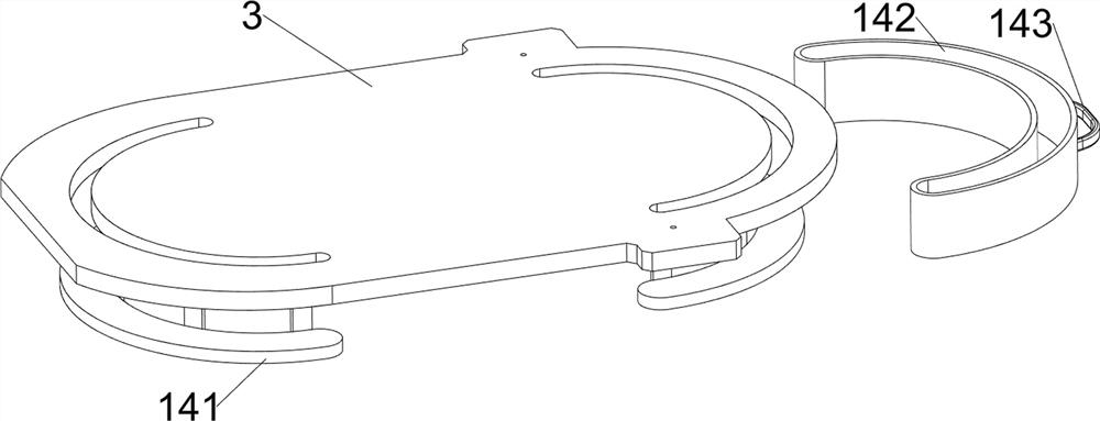
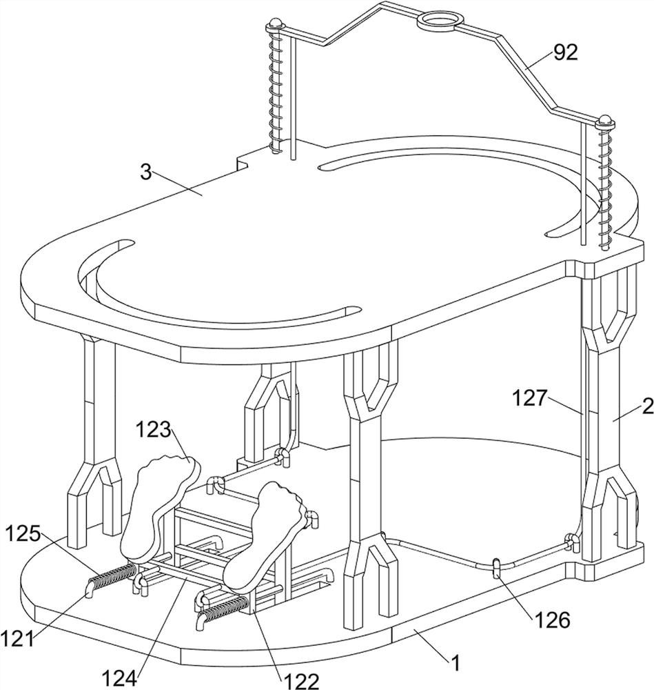
[0044] A new energy vehicle manufacturing brake pad polishing equipment, such as figure 1 As shown, it includes a base plate 1, a pole 2, an operation panel 3, a bracket 4, a motor 5, a spline 6, a shaft sleeve 7, a grinding disc 8, a pressing component 9 and a moving component 10, and the base plate 1 is provided with 4 The pole 2 is connected with the operation panel 3 between the tops of the poles 2, the right side of the top of the operation panel 3 is symmetrically provided with a support 4, the top of the support 4 is connected with a motor 5, and the output shaft of the motor 5 is provided with a spline 6, The spline 6 is slidably provided with a shaft sleeve 7 , the bottom of the shaft sleeve 7 is provided with a grinding disc 8 , the right side of the top of the operating panel 3 is provided with a pressing assembly 9 , and the top of the operating panel 3 is provided with a moving assembly 10 .

[0045] The staff can place the brake pads on the moving assembly 10, an...

Embodiment 2

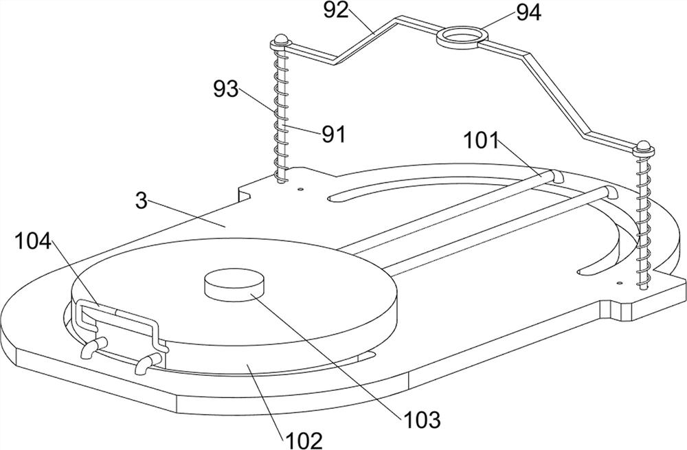
[0047] On the basis of Example 1, such as figure 2 As shown, the pressing assembly 9 includes a guide rod 91, a pressure rod 92, a first spring 93 and an annulus 94, and the right side of the top of the operating panel 3 is symmetrically provided with a guide rod 91, and the guide rod 91 is slidably provided with a pressure rod. 92, a circular ring 94 is connected between the compression rods 92, and the circular ring 94 cooperates with the lower part of the bushing 7, and a first spring 93 is connected between the bottom of the compression rod 92 and the guide rod 91.

[0048] The staff can push the pressure rod 92 to move downward to drive the ring 94 to move downward, thereby driving the shaft sleeve 7 and the grinding disc 8 to move downward for grinding. At this time, the first spring 93 is compressed, and after the grinding is completed, stop pushing the pressure rod 92 , the first spring 93 resets and drives the ring 94 and its upper parts to move upwards and resets th...

Embodiment 3

[0052] On the basis of Example 2, such as Figure 3 to Figure 6 As shown, clamping assembly 11 is also included, and clamping assembly 11 includes special-shaped block 111, wedge bar 112, clip block 113, second spring 114, fixed bar 115 and special-shaped bar 116, and both sides of the front and back sides of placing table 102 top A special-shaped block 111 is provided, and the outside of the special-shaped block 111 is slidingly provided with a wedge-shaped rod 112. The inside of the wedge-shaped rod 112 is provided with a clamping block 113, and two second springs 114 are connected between the outside of the clamping block 113 and the wedge-shaped rod 112. The front and rear sides of the plate 3 are symmetrically provided with fixed rods 115, and between the fixed rods 115 on the same side are provided with special-shaped rods 116, and the special-shaped rods 116 are all matched with the wedge-shaped rods 112 on the same side.

[0053]After placing the brake pads, the placin...


PUM


Abstract

The invention relates to grinding equipment, in particular to brake pad grinding equipment for new energy automobile manufacturing, and particularly provides brake pad grinding equipment for new energy automobile manufacturing and capable of achieving manual accurate placement, cooperating with grinding, flexibly controlling the grinding speed and improving the grinding efficiency. The brake pad grinding equipment for new energy automobile manufacturing comprises a bottom plate, supports, a motor and a shaft sleeve; multiple supporting rods are arranged on the bottom plate, and an operation plate is connected among the tops of the supporting rods; the supports are symmetrically arranged on one side of the top of the operation plate; the motor is connected between the tops of the supports, and a spline is arranged on an output shaft of the motor; and the shaft sleeve is arranged on the spline in a sliding manner, and a grinding disc is arranged on the lower portion of the shaft sleeve. The grinding disc is driven to rotate and meanwhile move downwards to grind a brake pad, and the basic functions of the equipment are achieved.

Description

technical field [0001] The invention relates to a grinding device, in particular to a brake pad grinding device for new energy automobile manufacturing. Background technique [0002] Brake pads are also called brake pads. In the braking system of a car, brake pads are the most critical safety parts. The brake pads play a decisive role in the quality of all braking effects. Brake pads are generally made of steel plates, adhesive insulation layers and friction Composed of blocks, the steel plate should be painted to prevent rust, and the SMT-4 furnace temperature tracker is used to detect the temperature distribution during the painting process to ensure the quality. [0003] At present, the grinding of brake pads is generally done manually one by one. The manual placement is inaccurate and the grinding efficiency is low. Therefore, it is necessary to design a new energy vehicle manufacturing with manual precise placement, combined with grinding, flexible control of grinding s...

Claims


Application Information

Patent Timeline
Patent Type & Authority Applications(China)
IPC IPC(8): B24B19/28B24B55/00B24B55/06B24B41/06B24B41/00
CPCB24B19/28B24B55/00B24B55/06B24B41/06B24B41/005B24B41/00
Inventor 陈艳伟邹琦许兴广
Owner LUOHE VOCATIONAL TECH COLLEGE
Why Eureka
Try Eureka