Cross-flow fan blade welding robot with good heat dissipation effect

A technology for welding robots and cross-flow fan blades, which is applied in the direction of electromechanical devices, chemical instruments and methods, cooling/ventilation devices, etc., can solve the problems of reduced processing efficiency, time-consuming and laborious, and low accuracy of fan blade position adjustment, reaching the extended position Accurate, guaranteed cooling effect, guaranteed effect of welding efficiency

Pending Publication Date: 2021-08-06
SHENZHEN SIJIECHUANG TECH CO LTD
View PDF3 Cites 0 Cited by
  • Summary
  • Abstract
  • Description
  • Claims
  • Application Information

AI Technical Summary

Problems solved by technology

During the welding process of the traditional cross-flow fan blade, the operator needs to adjust and fix the position of the fan blade, which is time-consuming and laborious, and the position adjustment accuracy of the fan blade is not high; on the other hand, the operator needs to continuously change the position of the fan blade during the welding process. point, which further leads to the reduction of processing efficiency, so there are certain limitations

Method used


Image

  • Cross-flow fan blade welding robot with good heat dissipation effect
  • Cross-flow fan blade welding robot with good heat dissipation effect
  • Cross-flow fan blade welding robot with good heat dissipation effect

Examples


Embodiment Construction

[0030] The technical solutions in the embodiments of the present invention will be clearly and completely described below in conjunction with the accompanying drawings in the embodiments of the present invention. Obviously, the described embodiments are only some of the embodiments of the present invention, not all of them. In the present invention, terms such as "installation", "setting", "connection", "fixation" and "rotary connection" should be understood in a broad sense unless otherwise clearly specified and limited, for example, it can be a fixed connection or a It is a detachable connection, or integrated; it can be a mechanical connection or an electrical connection; it can be a direct connection or an indirect connection through an intermediary, it can be the internal communication of two components or the interaction relationship between two components, Unless otherwise clearly defined, those skilled in the art can understand the specific meanings of the above terms i...


PUM


Abstract

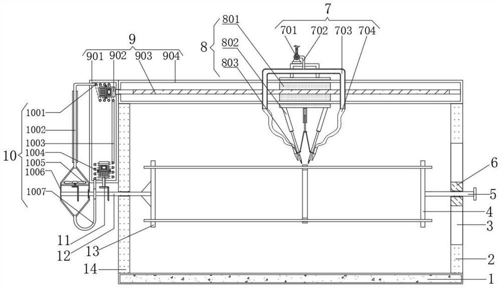
The invention discloses a cross-flow fan blade welding robot with a good heat dissipation effect. The cross-flow fan blade welding robot comprises an installation base, a first side supporting plate and a second side supporting plate are fixedly installed at the two ends of the outer wall of the top of the installation base correspondingly, and fan blade bearing mechanisms are installed on the opposite sides of the first side supporting plate and the second side supporting plate. A moving mechanism is installed at the top end of the first side supporting plate and the top end of the second side supporting plate, a welding operation mechanism is installed at one end of the moving mechanism, a smoke extraction mechanism is fixedly installed on the welding operation mechanism, and the moving mechanism comprises an end frame fixedly installed at the top end of the first side supporting plate and the top end of the second side supporting plate. The inner wall of the middle end of the end frame is connected with a threaded lead screw through a bearing in a rotating mode. By means of a stepping motor, a rotating shaft rod can be driven to rotate through transmission conical teeth, and therefore fan blades on fan blade inserting grooves are driven to rotate at a fixed frequency, automatic conversion of welding spots is achieved, and the welding efficiency of the fan blades can be guaranteed through the cooperation of the arranged moving mechanism.

Description

technical field [0001] The invention relates to the technical field of cross-flow fan blade processing, in particular to a cross-flow fan blade welding robot with good heat dissipation effect. Background technique [0002] The cross-flow fan, also known as the cross-flow fan, was first proposed by the French engineer Molt in 1892. The impeller is multi-leaf, long cylindrical, with forward multi-wing blades. When the impeller rotates, the airflow enters the cascade from the opening of the impeller, passes through the inside of the impeller, and is discharged into the volute from the cascade on the other side to form a working airflow. The flow of the airflow in the impeller is very complicated, the airflow velocity field is unstable, and there is a vortex in the impeller, and the center is located near the volute tongue. The existence of the vortex makes the output end of the impeller generate a circulating flow, and outside the vortex, the flow line of the air flow inside t...

Claims


Application Information

Patent Timeline
IPC IPC(8): B29C65/78B29C65/02B08B15/04H02K9/19B29L31/08
CPCB29C65/7811B29C65/02B29C66/0342B08B15/04H02K9/19B29L2031/085
Inventor 刘剑虹胡啸涂东东郭俊峰
Owner SHENZHEN SIJIECHUANG TECH CO LTD
Why Eureka
Try Eureka