
Automatic temperature control device of ground source heat pump

A ground source heat pump, automatic temperature control technology, applied in the direction of household heating, heating methods, household heating, etc., can solve the problems of insufficient stability, inconvenient operation, and inability to understand temperature changes more intuitively, and achieve convenient temperature adjustment. , the effect of improving controllability

Pending Publication Date: 2021-08-06
苏州百佳信能源科技有限公司
View PDF0 Cites 0 Cited by
  • Summary
  • Abstract
  • Description
  • Claims
  • Application Information

AI Technical Summary

Problems solved by technology

[0012] The purpose of the present invention is to provide an automatic temperature control device for ground source heat pumps in view of the deficiencies of the prior art, so as to solve the problem in the background technology that it does not have an automatic temperature control function, is inconvenient to operate, and cannot understand temperature changes more intuitively. The situation, the water quality problem of the heat source cannot be solved, it is easy to cause pipeline blockage, inconvenient maintenance, it needs to be disassembled, the heat dissipation efficiency is poor, and the normal operation of the equipment is affected, the installation is inconvenient, and the installation is not stable enough

Method used


Image

  • Automatic temperature control device of ground source heat pump
  • Automatic temperature control device of ground source heat pump
  • Automatic temperature control device of ground source heat pump

Examples


Embodiment Construction

[0041] The following will clearly and completely describe the technical solutions in the embodiments of the present invention with reference to the accompanying drawings in the embodiments of the present invention. Obviously, the described embodiments are only some, not all, embodiments of the present invention. Based on the embodiments of the present invention, all other embodiments obtained by persons of ordinary skill in the art without making creative efforts belong to the protection scope of the present invention.

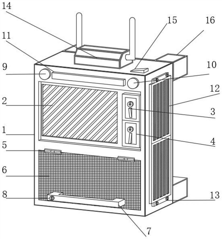
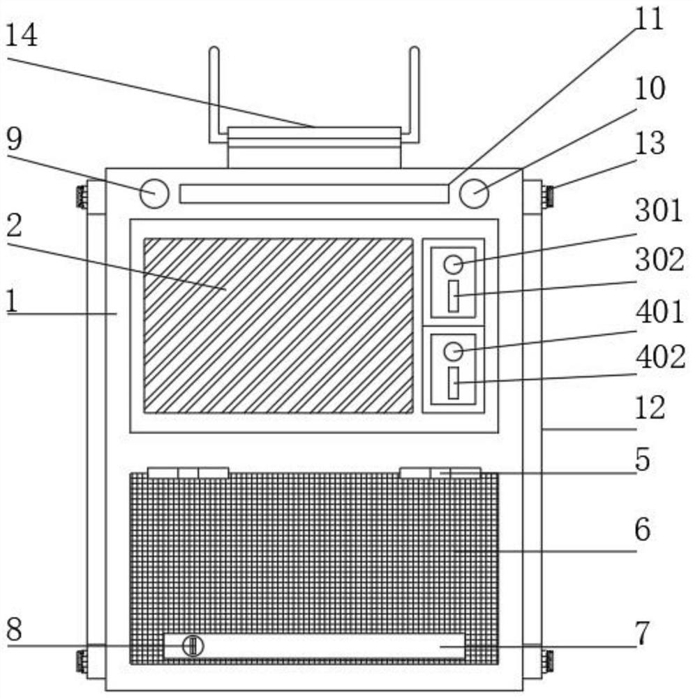
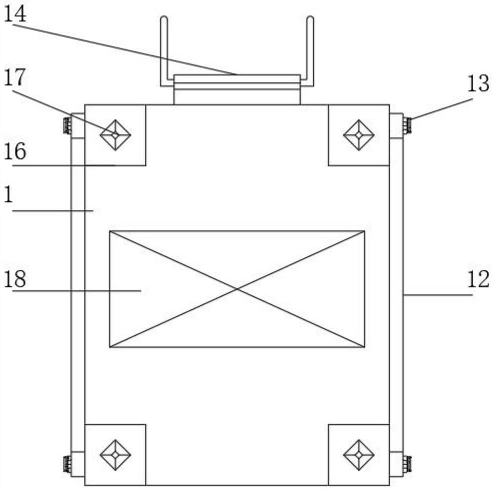
[0042] see Figure 1-9 , in this embodiment: including the device main body 1, the front surface of the device main body 1 is provided with a touch screen display 2, and the touch screen display 2 is located on the front side of the device main body 1, and is sequentially provided with a temperature rise control component 3 and a temperature drop control component 4, The front end of the main body 1 of the device is located at the bottom of the touch screen di...


PUM


Abstract

The invention discloses an automatic temperature control device for a ground source heat pump. The automatic temperature control device comprises a device main body, wherein a touch screen display is arranged on the front end surface of the device main body; a temperature rise control assembly and a temperature reduction control assembly are sequentially arranged on the side, located on the front end surface of the device main body, of the touch screen display; two sets of hinge portions are arranged at the position, located at the bottom of the touch screen display, of the front end surface of the device main body; a maintenance door is arranged at the bottoms of the hinge portions; a handle is arranged below the front end surface of the maintenance door; a self-locking piece is arranged at the front end of the handle; and a normal operation indicator lamp and an equipment fault indicator lamp are arranged on two sides of the top of the front end of the device main body respectively. According to the automatic temperature control device for the ground source heat pump, a heat dissipation plate is arranged, so that the device has better heat dissipation performance, and meanwhile, dust can be effectively prevented from entering the device; a fixing portion and a mounting wedge block are arranged, so that the device is more stable while being convenient to mount; and a cyclone desander is arranged, so that water of a heat source is screened, and impurities in the water are prevented from entering a pipeline to cause blockage.

Description

technical field [0001] The invention relates to the technical field of ground source heat pumps, in particular to an automatic temperature control device for ground source heat pumps. Background technique [0002] The ground source heat pump is a device that transfers low-grade heat energy to high-grade heat energy by inputting a small amount of high-grade energy (such as electric energy, etc.) from shallow terrestrial energy. Usually the ground source heat pump consumes 1kwh of energy, and the user can get more than 4kwh of heat or cold. [0003] The ground source heat pump is a heating central air conditioning system composed of a water ground source heat pump unit, a geothermal energy exchange system, and a building system, which uses rock and soil, stratum soil, groundwater or surface water as a low-temperature heat source. According to the different forms of geothermal energy exchange systems, ground source heat pump systems are divided into buried pipe ground source h...

Claims


Application Information

Patent Timeline
Patent Type & Authority Applications(China)
IPC IPC(8): F24F5/00F24F11/52F24F11/526F24F11/58F24F11/89F24F13/20F24F13/32F24F13/30
CPCF24F5/001F24F5/005F24F13/20F24F13/30F24F13/32F24F2005/0057F24F11/52F24F11/526F24F11/58F24F11/89Y02B10/40
Inventor 杨海成王伟
Owner 苏州百佳信能源科技有限公司
Learn More