Target speed estimation method based on sub-aperture radar interference

A technology of target velocity and sub-aperture, which is applied in the direction of measuring device, radio wave measurement system, radio wave reflection/reradiation, etc., can solve the problem of inability to distinguish whether the displacement comes from the horizontal direction or the vertical direction, the ambiguity of the surface deformation direction of the satellite interferometric radar, Unable to obtain 3D deformation and other problems, to achieve reliable technical support, improve imaging quality, and improve technical support

Pending Publication Date: 2021-08-06
GUILIN UNIVERSITY OF TECHNOLOGY
View PDF4 Cites 0 Cited by
  • Summary
  • Abstract
  • Description
  • Claims
  • Application Information

AI Technical Summary

Problems solved by technology

However, the radar measures the slant distance, so it is impossible to tell whether the displacement is from the horizontal direction or the vertical direction, that is, there is direction ambiguity
The satellite interferometric radar measurement only obtains the surface deformation component along the radar line of sight (LoS), and cannot obtain the three-dimensional deformation of the real surface (vertical, east-west, and north-south deformations), that is, the satellite interferometric radar surface deformation direction is blurred, These shortcomings limit the use of satellite interferometric radar in the field of real surface three-dimensional deformation monitoring such as land subsidence, landslides, volcanic activities, and earthquakes.
[0005] However, satellite interferometric radar deformation observation has the disadvantage of inherent direction ambiguity in slant distance measurement, and it is easy to be disturbed by systematic errors caused by surface deformation, resulting in the problem of space-time loss of coherence. Therefore, we propose a sub-aperture radar interferometric method based on The target speed estimation method of

Method used


Image

  • Target speed estimation method based on sub-aperture radar interference
  • Target speed estimation method based on sub-aperture radar interference
  • Target speed estimation method based on sub-aperture radar interference

Examples


Embodiment Construction

[0071] The following will clearly and completely describe the technical solutions in the embodiments of the present invention with reference to the accompanying drawings in the embodiments of the present invention. Obviously, the described embodiments are only some, not all, embodiments of the present invention.

[0072] The actual scene example is simulated below to illustrate the method for estimating the target speed based on sub-aperture radar interference of the present invention.

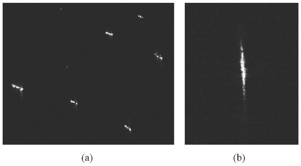
[0073] Example of actual scenario: figure 1 Comparison of RADARSAT-1 radar images of stationary ships and moving ships.

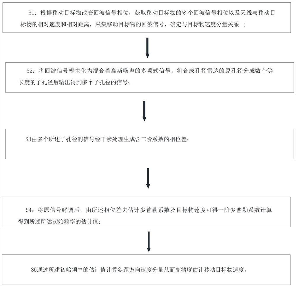
[0074] Such as figure 1 As shown, S1: change the echo signal phase according to the moving target, obtain multiple echo signal phases of the moving target and the relative speed and relative distance between the antenna and the moving target, collect the echo signal of the moving target, and determine the The relationship between the velocity components of the target obj...


PUM


Abstract

The invention discloses a target speed estimation method based on sub-aperture radar interference, and the method comprises the steps: dividing an original aperture of a synthetic aperture radar into a plurality of sub-apertures with equal length, outputting the sub-apertures to obtain signals of a plurality of sub-apertures, and carrying out the interference processing of the signals of the sub-apertures to generate a phase difference; and estimating the Doppler coefficient and the speed of the target object according to the phase difference. The method can be applied to long-distance, all-time, all-weather, macroscopic, large-scale and real-time detection of moving targets such as vehicles and ships, and overcomes the defects that the synthetic aperture radar image becomes fuzzy and generates position offset due to Doppler frequency shift generated by the moving targets.

Description

technical field [0001] The invention belongs to the technical field of radar monitoring, in particular to a target speed estimation method based on sub-aperture radar interference. Background technique [0002] With the acceleration of urban construction, surface deformation poses a potential risk to the hazards of human living environment. Surface deformation is mainly divided into instantaneous sudden deformation and continuous slow deformation. [0003] The main cause is land subsidence caused by large-scale urban engineering construction and excessive groundwater extraction. Land subsidence has the characteristics of slow development of causes, long duration and difficult prevention and control, which will cause great harm to high-speed railways, buildings and infrastructure, and lifeline projects. Therefore, long-term continuous monitoring of slow deformation such as land subsidence is very important. [0004] At present, the commonly used surface deformation monitor...

Claims


Application Information

Patent Timeline
Patent Type & Authority Applications(China)
IPC IPC(8): G01S13/58G01S7/41
CPCG01S13/589G01S7/418
Inventor 陈锟山杨莹任超
Owner GUILIN UNIVERSITY OF TECHNOLOGY
Why Eureka
Try Eureka