Flash memory device structure and manufacturing method thereof

A flash memory device and manufacturing method technology, applied in semiconductor devices, electric solid state devices, electrical components, etc., can solve the problem of inability to reduce the coupling effect from the select gate to the floating gate, etc. The effect of small coupling effects

Inactive Publication Date: 2021-08-06
HUA HONG SEMICON WUXI LTD
View PDF3 Cites 1 Cited by
  • Summary
  • Abstract
  • Description
  • Claims
  • Application Information

AI Technical Summary

Problems solved by technology

[0005] The present application provides a flash memory device structure and its manufacturing method, which can solve the problem in the related art that with the further shrinking of the flash memory device size, the coupling effect from the selection gate to the floating gate cannot be reduced by thinning the floating gate

Method used


Image

  • Flash memory device structure and manufacturing method thereof
  • Flash memory device structure and manufacturing method thereof
  • Flash memory device structure and manufacturing method thereof

Examples


Embodiment Construction

[0048] The technical solutions in the present application will be clearly and completely described below with reference to the accompanying drawings. Obviously, the described embodiments are a part of the embodiments of the present application, but not all of the embodiments. Based on the embodiments in the present application, all other embodiments obtained by those of ordinary skill in the art without creative work fall within the protection scope of the present application.

[0049] In the description of this application, it should be noted that the terms "center", "upper", "lower", "left", "right", "vertical", "horizontal", "inner", "outer", etc. The indicated orientation or positional relationship is based on the orientation or positional relationship shown in the accompanying drawings, which is only for the convenience of describing the present application and simplifying the description, rather than indicating or implying that the indicated device or element must have a ...


PUM

PropertyMeasurementUnit
thicknessaaaaaaaaaa
thicknessaaaaaaaaaa

Abstract

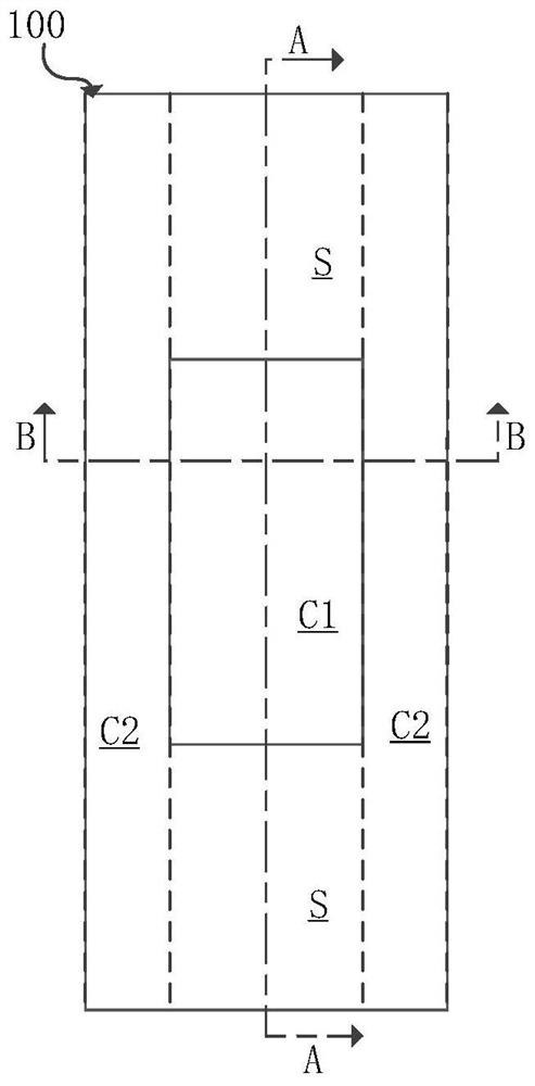
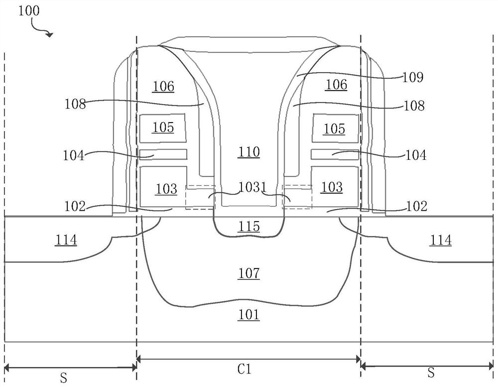
The invention relates to the technical field of semiconductor memory manufacturing, in particular to a flash memory device structure and a manufacturing method thereof. The flash memory device structure comprises a selection gate, a first split gate and a second split gate, wherein the selection gate is arranged between the first split gate and the second split gate; each of the first split gate and the second split gate comprises a floating gate structure and a control gate structure which are sequentially stacked from bottom to top; the floating gate structure comprises a floating gate dielectric layer and a floating gate polycrystalline silicon layer, the floating gate dielectric layer covers the flash memory cell region of the substrate layer, and the floating gate polycrystalline silicon layer covers the cell main body region of the floating gate dielectric layer; a first step structure which takes the upper surface of the floating gate polycrystalline silicon layer as an upper step surface, takes the upper surface of the isolation structure as a lower step surface and takes the side surface of the floating gate polycrystalline silicon layer as a step side surface is formed at the edge of the cell main body region; and the control gate structure comprises a polycrystalline silicon spacer layer and a control gate polycrystalline silicon layer, the polycrystalline silicon spacer layer covers the surface of the first step structure, and the control gate polycrystalline silicon layer covers the polycrystalline silicon dielectric layer.

Description

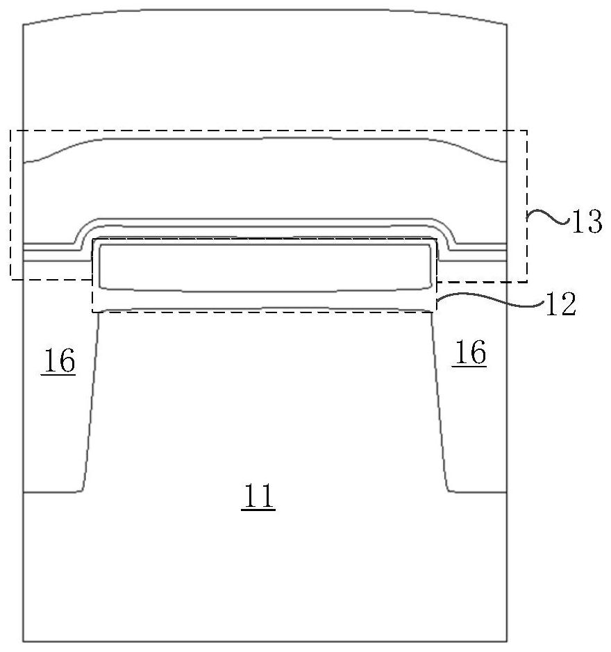
technical field [0001] The present application relates to the technical field of semiconductor memory fabrication, and in particular, to a structure of a flash memory device and a fabrication method thereof. Background technique [0002] Floating-gate split-gate flash memory is widely used in various embedded electronic products such as financial IC cards, automotive electronics and other fields because it is beneficial to save chip area and improve storage integration density. [0003] figure 1 A cross-sectional structural schematic diagram of the device structure of a 2-bit / cell (two bits per memory cell) split-gate floating-gate flash memory in the related art is shown. refer to figure 1 , the flash memory cell includes a substrate layer 11, a shallow trench isolation structure 16 is formed in the substrate layer between two adjacent flash memory cells, and a first split gate and a second split gate are formed on the substrate layer 11 of the flash memory cell The firs...

Claims


Application Information

Patent Timeline
Patent Type & Authority Applications(China)
IPC IPC(8): H01L27/11521H01L27/11536H01L27/11548H01L27/11558
CPCH10B41/30H10B41/44H10B41/50H10B41/60
Inventor 许昭昭
Owner HUA HONG SEMICON WUXI LTD
Why Eureka
Try Eureka