
Window coupling structure of filter

A coupling structure and filter technology, which is applied in the field of radio frequency communication, can solve the problems that the resonator does not have a window coupling structure and is inconvenient to realize, and achieves the effect of strong operability, simple structure and convenient installation

Pending Publication Date: 2021-08-06
SUZHOU PERFECT ELECTRONICS TECH
View PDF0 Cites 0 Cited by
  • Summary
  • Abstract
  • Description
  • Claims
  • Application Information

AI Technical Summary

Problems solved by technology

Resonators are installed in the inner cavity of existing air stripline filters, but generally there is no window coupling structure on the resonator, and even if it is desired to set a window coupling structure on the resonator, it is not convenient to implement

Method used


Image

  • Window coupling structure of filter
  • Window coupling structure of filter

Examples


Embodiment Construction

[0015] The specific implementation manners of the present invention will be further described below in conjunction with the drawings and examples. The following examples are only used to illustrate the technical solution of the present invention more clearly, but not to limit the protection scope of the present invention.

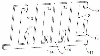
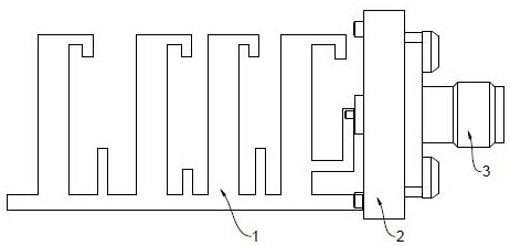
[0016] Such as figure 1 with figure 2 As shown, the present invention provides a window coupling structure of a filter, and a resonator 1 is arranged in the inner cavity of the filter; the resonator 1 includes: a row of resonant rods 12 extending downward from the top of the resonant rods 12 The negative coupling section 13 is out, and the positive coupling section 14 is located between two adjacent resonant rods 12 and extends upward.

[0017] more specific:

[0018] The resonator 1 is a chip resonator 1; the chip resonator 1 includes a strip-shaped base 11; the row of resonant rods 12 is formed by extending upward from the strip-shaped base 11, and th...


PUM


Abstract

The invention discloses a window coupling structure of a filter. A resonator in an inner cavity of the filter is provided with a row of resonance rods, negative coupling sections extending downwards from the tops of the resonance rods, and positive coupling sections located between every two adjacent resonance rods and extending upwards. The negative coupling sections and the positive coupling sections are arranged on the resonator, and the window coupling structure is simple in structure, convenient to machine and install, high in operability and high in production efficiency.

Description

technical field [0001] The invention relates to the technical field of radio frequency communication, in particular to a window coupling structure of a filter. Background technique [0002] The transceiver filter is a key component of the radio frequency front end of the mobile base station, and its performance directly affects the communication quality. Resonators are installed in the inner cavity of existing air stripline filters, but generally there is no window coupling structure on the resonators, and even if it is desired to install a window coupling structure on the resonators, it is not convenient to implement. Contents of the invention [0003] The object of the present invention is to provide a window coupling structure of a filter. A resonator is arranged in the inner cavity of the filter; the resonator includes: a row of resonant rods, a negative coupling segment, and a positive coupling segment located between two adjacent resonant rods and extending upward. ...

Claims


Application Information

Patent Timeline
IPC IPC(8): H01P7/08H01P7/00H01P1/207
CPCH01P1/207H01P7/00H01P7/08
Inventor 谭志平肖艺叶志锋
Owner SUZHOU PERFECT ELECTRONICS TECH
Learn More