
Method for improving communication delay in distributed secondary control of direct current micro-grid

A DC micro-grid, communication delay technology, applied in the direction of DC network circuit device, AC network voltage adjustment, power transmission AC network, etc., can solve the problems of large communication pressure, not given the impact of improving communication delay, etc., to reduce communication pressure , Enhance anti-communication delay ability, improve the effect of current sharing accuracy

Inactive Publication Date: 2021-08-06
ANHUI UNIVERSITY OF TECHNOLOGY
View PDF0 Cites 2 Cited by
  • Summary
  • Abstract
  • Description
  • Claims
  • Application Information

AI Technical Summary

Problems solved by technology

In order to achieve distributed secondary control, the document "AnImproved Droop Control Method for DC Microgrids Based on Low Bandwidth Communication With DC Bus Voltage Restoration and Enhanced Current SharingAccuracy" IEEE Transactions on Power Electronics (vol.29, no.4, pp.1800-1812 ), a distributed secondary control scheme is proposed, which collects voltage and current information of other units through a low-bandwidth communication network to achieve secondary control voltage compensation. However, this method is not sparsely communicated and still bears a large communication pressure; In the paper "Distributed Secondary Control in DC Microgrid with Low-Bandwidth Communication Link" Power Electronics and Drive Systems Technologies Conference (2016, pp.641-645), the consensus algorithm is introduced into the distributed secondary control, which only needs to communicate with neighboring units Communication can achieve a good control effect; the document "Effect of Communication Delay on Consensus-Based Secondary Controllers in DC Microgrid" IEEE Transactions on Industrial Electronics (vol.68, no.4, pp.3202-3212), the paper demonstrates The influence of communication delay on distributed secondary control and gives a delay margin, but it does not give an improvement plan to improve the influence of communication delay

Method used


Image

  • Method for improving communication delay in distributed secondary control of direct current micro-grid
  • Method for improving communication delay in distributed secondary control of direct current micro-grid
  • Method for improving communication delay in distributed secondary control of direct current micro-grid

Examples


Embodiment Construction

[0047] The following will clearly and completely describe the technical solutions in the embodiments of the present invention with reference to the accompanying drawings in the embodiments of the present invention. Obviously, the described embodiments are only some, not all, embodiments of the present invention. Based on the embodiments of the present invention, all other embodiments obtained by persons of ordinary skill in the art without creative efforts fall within the protection scope of the present invention.

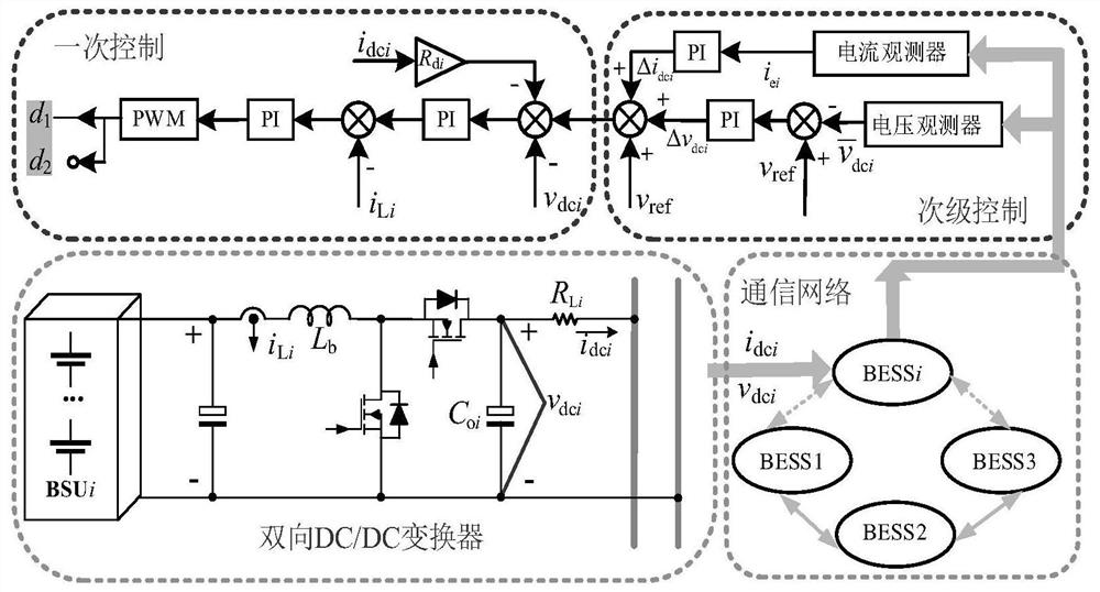
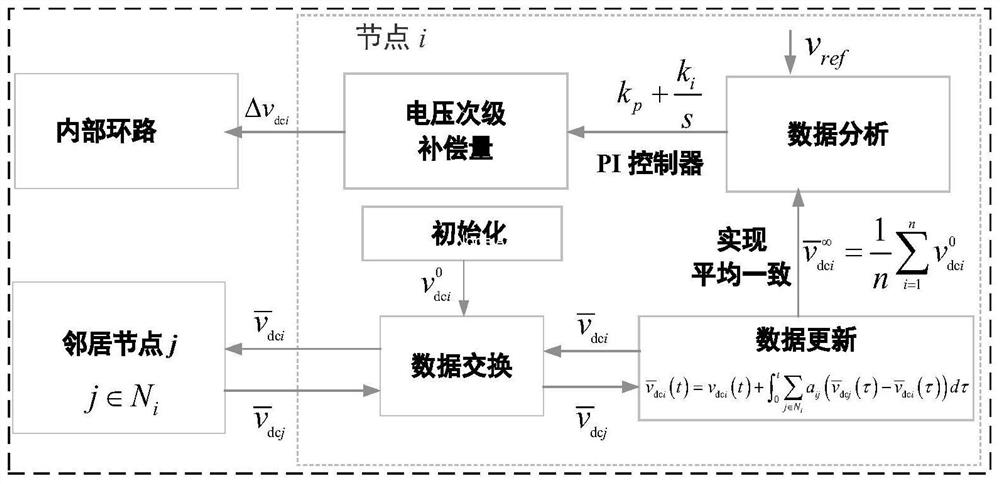
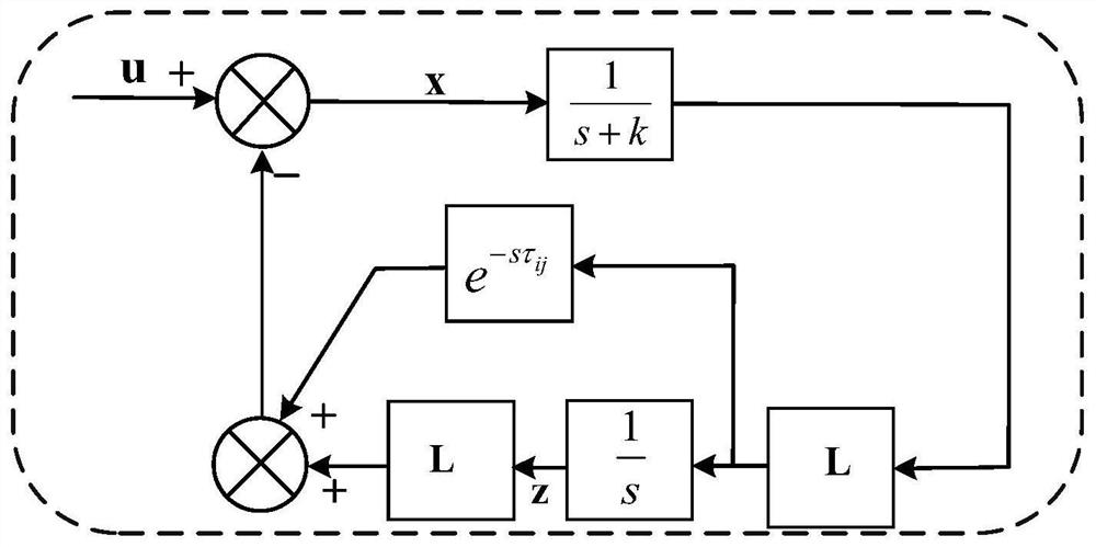
[0048] In the present invention, three interconnected DC micro-grid parallel units are set, and each unit is parallel connected to the DC bus through line resistance, and the rated voltage of the DC bus is 48V. Using the improved consensus algorithm for communication delay in distributed secondary control, the implementation of this method needs to complete the following steps:

[0049] S1. First, add a fixed coefficient droop control to each parallel converter uni...


PUM


Abstract

The invention provides an improvement method for improving communication delay in distributed secondary control of a direct current micro-grid, which is mainly used for improving bus voltage drop caused by droop control and further improving the current sharing precision of output current of a plurality of parallel units at the same time, and therefore, the communication pressure of geographically adjacent direct current micro-grid units is reduced, and the overall performance of the direct current micro-grid system is improved. The improved communication delay algorithm provided by the invention mainly aims at the time delay in the communication link of a consistency algorithm, and solves the problems that the consistency algorithm cannot converge and the output of the direct current micro-grid is unstable due to the communication delay.

Description

technical field [0001] The invention relates to the technical field of direct current microgrid control, in particular to an improved method for communication delay in distributed secondary control of direct current microgrid. Background technique [0002] The distributed secondary control of DC microgrid has attracted much attention because of its better compensation effect on bus voltage drop, less communication required, high reliability, and easy plug-and-play. In order to achieve distributed secondary control, the document "AnImproved Droop Control Method for DC Microgrids Based on Low Bandwidth Communication With DC Bus Voltage Restoration and Enhanced Current SharingAccuracy" IEEE Transactions on Power Electronics (vol.29, no.4, pp.1800-1812 ), a distributed secondary control scheme is proposed, which collects voltage and current information of other units through a low-bandwidth communication network to achieve secondary control voltage compensation. However, this me...

Claims


Application Information

Patent Timeline
Patent Type & Authority Applications(China)
IPC IPC(8): H02J3/12H02J3/36H02J3/38H02J13/00H02J1/00
CPCH02J3/12H02J3/36H02J3/38H02J1/001H02J13/00006H02J13/00032Y02E40/70Y02E60/00Y02E60/60Y04S10/12Y04S40/12
Inventor 刘宿城李润陈莉刘晓东
Owner ANHUI UNIVERSITY OF TECHNOLOGY
Learn More