Dust and ash removal device for waste incineration

A technology for cleaning ash device and waste incineration, which is used in transportation and packaging, separation of dispersed particles, chemical instruments and methods, etc., can solve the problems of inability to remove dust, easy adhesion of dust, difficult to clean inside the device and filter structure, etc. To achieve the effect of good use, to achieve the cleaning function, to achieve the effect of the exhaust function

Pending Publication Date: 2021-08-10
亳州洁能电力有限公司
View PDF6 Cites 3 Cited by
  • Summary
  • Abstract
  • Description
  • Claims
  • Application Information

AI Technical Summary

Problems solved by technology

[0004] The purpose of the present invention is to provide a dust removal device for garbage incineration, which filters the exhaust gas through a filter bag, and reminds the operator to clean the dust in time by setting a reminding dust removal mechanism, so as to avoid dust accumulation in the dust discharge hopper. Affecting the filtering operation, the air injection pipe sprays air towards the filter bag to blow away the particles attached to the filter bag, so as to realize the cleaning of the filter bag. The dust removal box is continuously vibrated by repeated knocking, so that the dust attached to the inner wall of the dust removal box Particles fall to realize the cleaning inside the dust removal box, which solves the problem that the dust accumulated in the dust collection chamber cannot be cleaned out in time when the waste gas generated in the waste incineration process is removed, and the dust is easy to adhere to the inner wall of the device and In the filter holes of the filter structure, it is difficult to clean the inside of the device and the filter structure

Method used


Image

  • Dust and ash removal device for waste incineration
  • Dust and ash removal device for waste incineration
  • Dust and ash removal device for waste incineration

Examples


Embodiment 1

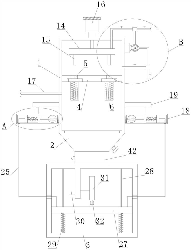
[0030] like Figure 1-5As shown, the present invention proposes a dust removal and ash removal device for garbage incineration, including a dust removal box 1, an ash discharge bucket 2, a fixed box 3 and a dust discharge pipe 33, and the ash discharge bucket 2 is fixedly arranged at the bottom of the dust removal box 1 , the ash discharge hopper 2 collects the dust generated in the dust filtering process, the fixed box 3 is located under the dust removal box 1 and is fixedly connected with the ash discharge hopper 2 through bolts, and the dust discharge pipe 33 is fixedly arranged on the ash discharge hopper 2, and the dust discharge pipe 33 is used to discharge the dust in the dust discharge hopper 2, and the dust discharge pipe 33 is provided with a valve, the valve is used to control the discharge of dust, and the dust discharge hopper 2 is provided with a reminder cleaning mechanism 42, which is used to Remind the operator to clean up the accumulated dust in the ash disch...

Embodiment 2

[0034] like Image 6 As shown, the present embodiment is basically the same as Embodiment 1. Preferably, the reminder cleaning mechanism 42 includes a detection chamber 34, a bearing plate 35, a pressure sensor 36, a third spring 37, a buzzer 38 and a processor; The inner bottom of the bucket 2 is provided with a detection cavity 34, and the bearing plate 35 is horizontally arranged in the detection cavity 34, and the dust generated in the filtering process falls and gathers on the bearing plate 35, and the weight of the dust makes the bearing plate 35 drop, and the third spring 37 is vertically arranged in the detection chamber 34 and connected with the bottom of the bearing plate 35, the third spring 37 is used to lift the bearing plate 35 to return to its original position after unloading; the pressure sensor 36 is fixed and installed in the detection chamber 34 by bolts Inside, and the pressure sensor 36 is below the bearing plate 35, when the internal dust reaches a certa...

Embodiment 3

[0036] like Figure 7 As shown, this embodiment is basically the same as Embodiment 1. Preferably, a second limiting cavity 41 is opened in the knocking ball 20, and a second sliding block 39 is slidably arranged in the second limiting cavity 41, and the second limiting cavity The cavity 41 plays a limiting role on the second slider 39, and the second slider 39 slides in the second limiting cavity 41; the movable rod 21 extends into the second limiting cavity 41 and is connected with the second slider 39, The second slide block 39 is equipped with a fourth spring 40 on the side facing away from the second slide block 39. When the knocking ball 20 hits the dust removal box 1, the second slide block 39 slides in the second spacer cavity 41, and the fourth spring 40 The spring 40 is elastically deformed to play a buffering role.


PUM


Abstract

The invention belongs to the technical field of garbage treatment, aims at solving the problems that when waste gas generated in the garbage incineration process is treated, dust in a dust collection chamber cannot be cleaned in time, and the inner wall of a dust filtering device and a filtering structure are difficult to effectively clean, and particularly relates to a dust removal and ash removal device for garbage incineration. The device comprises a dust removal box, a dust discharge hopper, a fixed box and a dust discharge pipe, the dust discharge hopper is fixedly arranged at the bottom of the dust removal box, the fixed box is located below the dust removal box, a dust removal reminding mechanism is arranged on the dust discharge hopper, a connecting base is fixedly installed in the dust removal box through bolts, multiple sets of filter bags are arranged at the bottom of the connecting base, and an exhaust port is correspondingly formed in the connecting base; and a waste gas conveying pipe is mounted on the dust removal box. By arranging the dust removal reminding mechanism, an operator can be reminded to clean dust in the dust discharging hopper in time, and dust particles attached to the inner wall of the filter box and the surface of the filter bag can be effectively cleaned.

Description

technical field [0001] The invention relates to the technical field of garbage treatment, in particular to a dust removal device for garbage incineration. Background technique [0002] Garbage incineration is the process of reducing the volume of garbage through oxidation at high temperature through appropriate thermal decomposition, combustion, melting and other reactions, and becomes residue or molten solid matter. Garbage incineration is an older traditional method of garbage disposal. After the garbage is treated by incineration, the reduction effect is remarkable, the land is saved, various pathogens can be eliminated, and toxic and harmful substances can be converted into harmless substances, so the garbage incineration method has become one of the main methods of urban garbage disposal; garbage During the incineration process, waste gas will be generated, and the waste gas contains a lot of dust, which needs to be filtered for dust treatment; [0003] In the Chinese ...

Claims


Application Information

Patent Timeline
Patent Type & Authority Applications(China)
IPC IPC(8): B01D46/00B01D46/02B01D46/04B01D46/44B01D46/48
CPCB01D46/023B01D46/446B01D46/48B01D46/04B01D46/79
Inventor 陈家刚李腾飞李加杜红山郭圣子刘恩
Owner 亳州洁能电力有限公司
Why Eureka
Try Eureka