
Sleeve equipment for preventing short pile from being frozen and pulled out in frozen earth area and using method

A casing equipment and casing technology, applied in sheet pile walls, protection devices, buildings, etc., can solve problems such as increasing project cost, and achieve the effects of saving project cost, low friction coefficient, and ensuring stability

Pending Publication Date: 2021-08-10
POWERCHINA XIBEI ENG
View PDF0 Cites 2 Cited by
  • Summary
  • Abstract
  • Description
  • Claims
  • Application Information

AI Technical Summary

Problems solved by technology

In areas with thick permafrost, in order to meet the pullout requirements of buildings, it is often necessary to increase the length of the pile body, which increases the project cost

Method used


Image

  • Sleeve equipment for preventing short pile from being frozen and pulled out in frozen earth area and using method
  • Sleeve equipment for preventing short pile from being frozen and pulled out in frozen earth area and using method
  • Sleeve equipment for preventing short pile from being frozen and pulled out in frozen earth area and using method

Examples


Embodiment 1

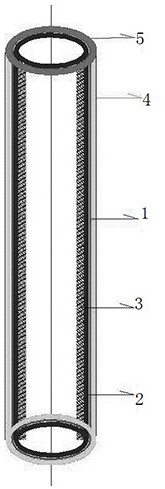
[0028] Such as figure 1 As shown, a kind of anti-short pile freeze-pull casing equipment in permafrost areas includes a casing 1 set outside the prefabricated pile, the inner wall of the casing 1 is coated with an adhesive layer 2, and the adhesive layer 2 is provided with a filling layer 3. The outer wall of the casing 1 is coated with a lubricating layer 4, and the inner wall of the upper end of the casing 1 is also connected with a sealing rubber ring 5.

[0029] The casing 1 is a PE pipe.

[0030] The adhesive layer 2 is adhesive glue sprayed on the inner wall.

[0031] The filling layer 3 is wood chips.

[0032] The lubricating layer 4 is a hydrophobic lubricating glue.

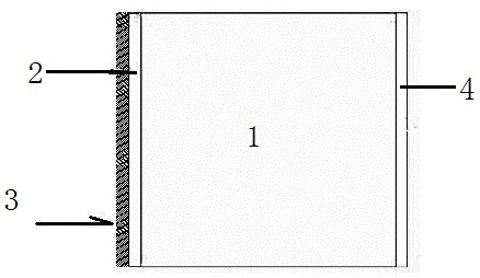
[0033] Such as figure 2 As shown, the casing 1 is hollow inside, and its inner diameter is about 5mm larger than the diameter of the prefabricated pile. The entire casing 1 is placed outside the prefabricated pile.

[0034] Spray the chipped wood chips on the adhesive layer 2, and the chipped wood ...

Embodiment 2

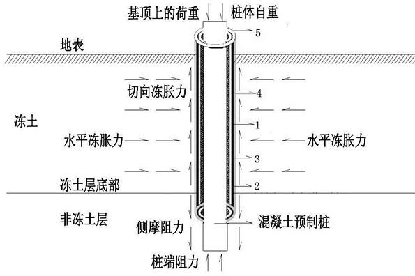
[0037] On the basis of Example 1, such as image 3 Shown, a kind of use method of anti-short pile freeze-pull casing equipment in permafrost region, comprises the following steps:

[0038] The casing is prefabricated, the adhesive glue is sprayed on the inner wall of the casing 1 to form an adhesive layer 2, and the hydrophobic lubricating glue is sprayed on the outer wall of the casing 1 to form a lubricating layer 4;

[0039] The filling layer is prefabricated, and the wood chips are sprayed on the inner wall of the casing 1, and the wood chips are stuck on the adhesive layer 2 to form the filling layer 3;

[0040] Place the prefabricated pile 6 and the casing 1 in the prepared hole, and insert the prefabricated pile 6 into the casing 1, and the upper end of the casing 1 is exposed to the surface,

[0041] Where the casing 1 and the pile body are exposed to the surface, a sealing rubber ring 5 is inserted into the gap between the inner wall of the casing 1 and the outer wal...


PUM


Abstract

The invention discloses sleeve equipment for preventing a short pile from being frozen and pulled out in a frozen earth area and a using method. The sleeve equipment comprises a sleeve arranged outside a precast pile in a sleeving mode; the inner wall of the sleeve is coated with a bonding layer; a filling layer is arranged on the bonding layer; the outer wall of the sleeve is coated with a lubricating layer; and the inner wall of the upper end of the sleeve is further connected with a sealing rubber ring. The sleeve is a PE pipe. The bonding layer is a bonding glue sprayed on an inner wall. The filling layer is made of wood chips. The lubricating layer is a hydrophobic lubricating glue. A tangential frost heaving force generated by frost heaving of thick-layer seasonal frozen soil is transferred to the sleeve, and the sleeve is used for bearing a frost cutting force and preventing the frost cutting force from acting on a pile body, so that the precast pile is prevented from being affected by the frost pulling effect. Therefore, the length of the precast pile can be shortened, and the construction cost is saved.

Description

technical field [0001] The invention belongs to the field of construction in thick-layer frozen soil areas, and in particular relates to a casing device and a use method for preventing short piles from freezing and pulling out in frozen soil areas. Background technique [0002] With the development of my country's power grid construction, more and more overhead transmission line projects need to pass through permafrost areas. Similarly, more and more photovoltaic power plants are built in high-altitude, high-altitude and permafrost areas with better lighting conditions. When carrying out foundation construction in permafrost regions, the influence of permafrost foundations on foundation forces must be considered, and reasonable foundation forms and calculation methods need to be selected, and measures to reduce frost heave must be taken. [0003] Permafrost is composed of a complex "four-item" system of solid mineral particles, ice inclusions and ice interlayers, bound and ...

Claims


Application Information

Patent Timeline
Patent Type & Authority Applications(China)
IPC IPC(8): E02D27/35E02D5/60E02D31/14
CPCE02D5/60E02D27/35E02D31/14
Inventor 严耿升苏盛伟胡向阳赵光竹高徐军赵成张婧宇鲁博曲鹏飞吴辉支再兴黄佳陈志源
Owner POWERCHINA XIBEI ENG
Learn More