Frame inclined energy dissipation supporting device

An energy-consuming support and frame technology, which is applied to building components, building structures, and earthquake resistance, can solve the problems of unfavorable replacement of damaged parts, unfavorable building reinforcement, and aggravation of earthquake disasters, so as to achieve easy repair, convenient reinforcement, The effect of improving structural strength

Pending Publication Date: 2021-08-10
HEBEI UNIV OF TECH
View PDF6 Cites 0 Cited by
  • Summary
  • Abstract
  • Description
  • Claims
  • Application Information

AI Technical Summary

Problems solved by technology

[0003] However, if the design of the frame system is unreasonable, the brittle failure of the structure under the action of the earthquake load will aggravate the earthquake disaster, threatening the safety of people's lives and property; in addition, the traditional frame system is difficult to repair after damage or the loss caused by irreparable damage is very huge, which is not conducive to Renewal and replacement of damaged parts after the earthquake is also not conducive to the reinforcement of buildings after the earthquake

Method used


Image

  • Frame inclined energy dissipation supporting device
  • Frame inclined energy dissipation supporting device
  • Frame inclined energy dissipation supporting device

Examples


Embodiment approach 1

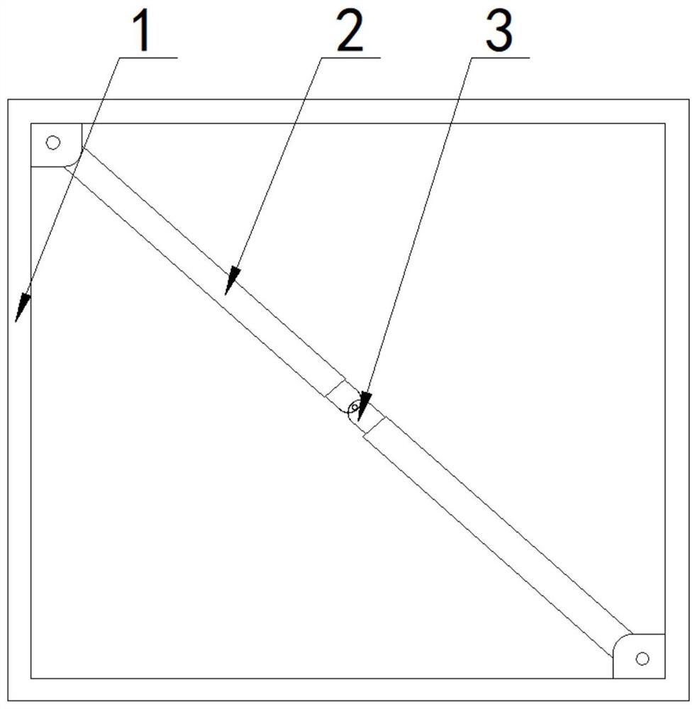
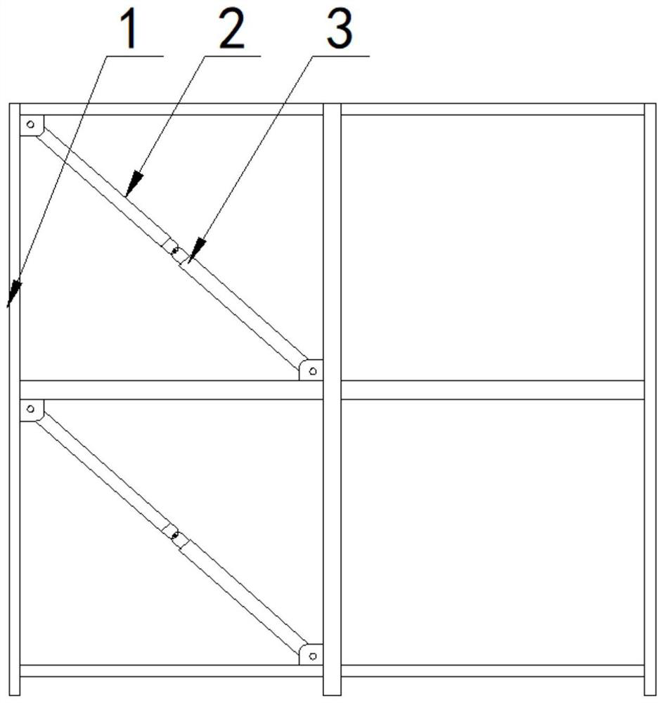
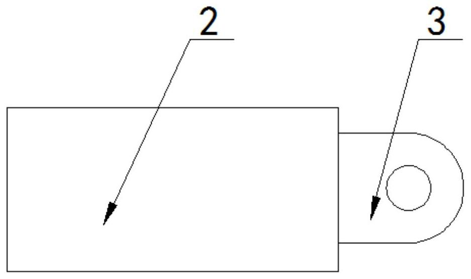
[0040] Please refer to image 3 , the connecting piece 3 is a connecting piece provided with a hinge hole and it is directly affixed to the free end of the support body 2; bars or steel plates with through holes; the low-yield steel bars or steel plates with through holes are respectively symmetrically distributed on both sides of the two hinged connecting pieces.

[0041] In this embodiment, the connecting piece is directly connected to the supporting body, and the connecting piece between the two supporting bodies can be hinged.

[0042] In this embodiment, the energy dissipation parts are low-yield steel bars or steel plates with through holes connected between the ends of the two supports 2; the low-yield steel bars or steel plates with through holes are respectively symmetrically distributed in The two sides of the two connecting pieces that are hinged to each other are as follows: Figure 3a and Figure 3b shown.

Embodiment approach 2

[0044] Please refer to Figure 4, the connector 3 includes: a first connecting steel plate 8 and a connecting piece connected to one side of the first connecting steel plate 8; Connecting steel plate 9; the energy dissipation element is a low-yield steel bar or a steel plate with a through hole connected between the two first connecting steel plates 8 and symmetrically located between the two connecting plates.

[0045] The difference from Embodiment 1 is that in this embodiment, the connecting piece is not directly connected to the support body, but is connected to the second connecting steel plate correspondingly provided on the support body through the first connecting steel plate. This design enhances this embodiment versatility.

[0046] In this embodiment, the energy dissipation member is a low-yield steel bar or a steel plate with a through hole that is connected between the two first connecting steel plates 8 and symmetrically located between the two connecting pieces...

Embodiment approach 3

[0048] Please refer to Figure 5 As shown, the connecting piece 3 is a cross-shaped joint connected to the support body 2, and the middle part of the cross-shaped joint extends with a horizontal connecting part integrally provided with it and has a hinge hole; the energy dissipation element is horizontally connected to two Low-yield steel bars or steel plates with through holes between the corresponding upper and lower ends of the cross joint.

[0049] exist Figure 5 Among them, the two connecting parts are hingedly connected through a horizontal connecting part.

[0050] Figure 5 Among them, the energy dissipation part is a low-yield steel bar or a steel plate with a through hole horizontally connected between the upper and lower ends of the two cross-shaped joints, respectively as Figure 5a and Figure 5b shown.


PUM


Abstract

The invention discloses a frame inclined energy dissipation supporting device. The device comprises a frame body, a plurality of supporting bodies arranged on the frame body and an energy dissipation assembly used for being connected with the supporting bodies, wherein the supporting bodies are obliquely arranged on the frame body, the two supporting bodies are oppositely arranged and connected through the energy dissipation assembly, the energy dissipation assembly comprises connecting pieces arranged at one ends of the two supporting bodies correspondingly and energy dissipation pieces arranged on the connecting pieces, the two connecting pieces are oppositely arranged, the free ends of the two connecting pieces are hinged to each other, and the energy dissipation pieces are used for connecting the ends of the two supporting bodies or used for connecting the ends of the two connecting pieces. According to the frame inclined energy dissipation supporting device, the node form is adopted, so that assembly is simple, and meanwhile connection of supports in a concrete frame structure is facilitated; and earthquake energy can be effectively absorbed during an earthquake, horizontal connecting rods and energy dissipation parts are convenient to replace after the earthquake, post-earthquake repair is easy, and post-earthquake building reinforcement is convenient.

Description

technical field [0001] The present disclosure generally relates to the technical field of building frames, and in particular to a frame oblique energy-dissipating support device. Background technique [0002] With the acceleration of the urbanization process, the development of the construction field and the continuous improvement of the technical level, coupled with the impact of environmental pollution and resource waste, the defects of poor environmental protection in the traditional building system are gradually exposed, and the prefabricated concrete structure has begun to become a building system. main types of . [0003] However, if the design of the frame system is unreasonable, the brittle failure of the structure under the action of the earthquake load will aggravate the earthquake disaster, threatening the safety of people's lives and property; in addition, the traditional frame system is difficult to repair after damage or the loss caused by irreparable damage is...

Claims


Application Information

Patent Timeline
Patent Type & Authority Applications(China)
IPC IPC(8): E04B1/98E04B1/344E04H9/02
CPCE04B1/98E04B1/3441E04H9/021E04H9/023E04H9/025
Inventor 戎贤张健新裴宗虎李艳艳刘平王理达张晓巍赵茜娅
Owner HEBEI UNIV OF TECH
Why Eureka
Try Eureka