Shaft end sealing structure for deepwater speed reducer and sealing performance testing device

A technology of shaft end sealing and sealing performance, which can be used in the use of liquid/vacuum for liquid tightness measurement, engine sealing, and measurement of fluid acceleration and deceleration rates. Affect the sealing performance and life of mechanical seals, achieve the best sealing performance and save manufacturing costs

Active Publication Date: 2021-08-10
YANSHAN UNIV
View PDF13 Cites 0 Cited by
  • Summary
  • Abstract
  • Description
  • Claims
  • Application Information

AI Technical Summary

Problems solved by technology

For ordinary contact mechanical seals, due to the huge water pressure, a huge pressure is generated between the sealing dynamic ring and the sealing static ring. When the reducer is running, the sealing dynamic ring and the sealing static ring rub against each other, which accelerates the wear of the friction surface. As a result, the sealing performance and life of the mechanical seal are affected, and there is no sealing test device for deep water reducer on the market
[0003] Aiming at the published patent application number 201710669154.3, a connection structure between the dynamic ring and the static ring of a mechanical seal is mainly aimed at the wedge-shaped surface of the static ring provided at one end of the sealed static ring. The wedge-shaped surface of the dynamic

Method used


Image

  • Shaft end sealing structure for deepwater speed reducer and sealing performance testing device
  • Shaft end sealing structure for deepwater speed reducer and sealing performance testing device
  • Shaft end sealing structure for deepwater speed reducer and sealing performance testing device

Examples


Embodiment Construction

[0029] In order to detailed the technical content, structural features of the present invention, the integration of the specification will be described in detail below.

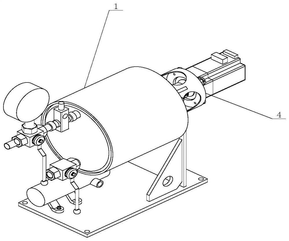
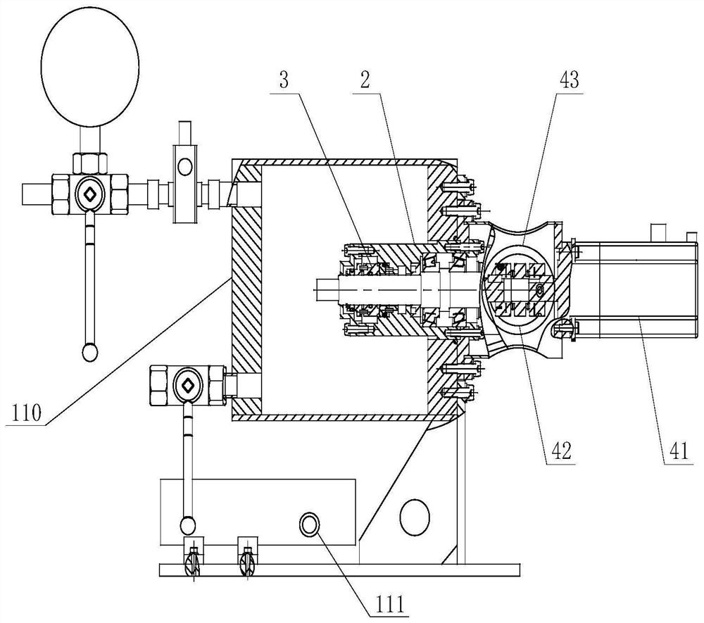
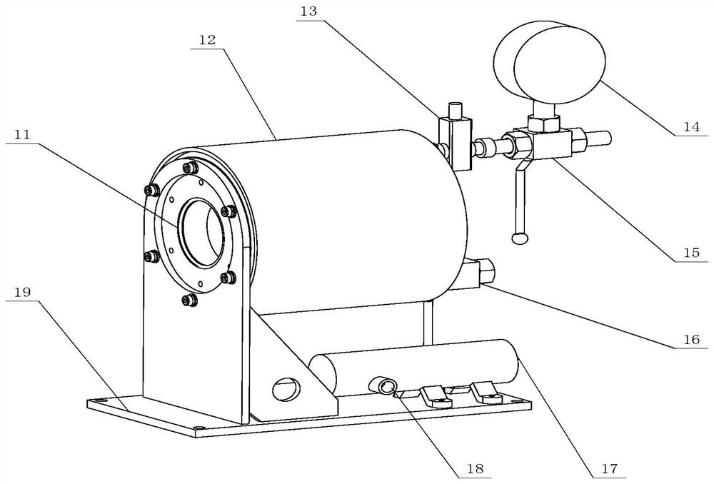
[0030]Shaft end sealing structure and sealing performance test device for deep water deceleration, such as figure 1 and figure 2 As shown, it includes a pressure vessel assembly 1, a housing assembly 2, a mechanical sealing assembly 3, and a drive assembly 4. The first end of the outer casing assembly 2 is located inside the pressure vessel assembly 1, and the second end of the outer casing assembly 2 and the first end of the second end of the pressure vessel assembly 1, the mechanical seal group 3 is located at the outer casing assembly 2. The inside, and the rotation shaft 21 of the outer casing assembly 2 is fixed, and the bell cover 42 of the drive assembly 4 and the second end 11 of the pressure vessel assembly 1 are connected.

[0031] The main body portion of the pressure vessel assembly 1 is welding, such...


PUM


Abstract

The invention provides a shaft end sealing structure for a deepwater speed reducer and a sealing performance testing device. The shaft end sealing structure for the deepwater speed reducer comprises a pressure vessel assembly, an outer shell assembly, a mechanical sealing assembly and a driving assembly; a first end of the outer shell assembly is located inside the pressure vessel assembly; a second end of the outer shell assembly is fixedly connected with a first end of a second end socket of the pressure vessel assembly; the mechanical sealing assembly is located in the outer shell assembly; and a bell jar of the driving assembly is connected with a second end of the second end socket of the pressure vessel assembly. In the mechanical sealing assembly, a square hole and an oval hole are separately formed in a first end of a sealing static ring in the radial direction; the sealing static ring is connected with a first end of a sealing movable ring; a spring seat is connected with a second end of the sealing movable ring through a second pin shaft; and a spring is located in a spring hole of the spring seat. According to the invention, the square-oval double-layer composite texture machined on the sealing static ring enables a liquid film between the end faces of a mechanical sealing friction pair to generate a dynamic pressure effect, and non-contact, high-stability and low-abrasion operation of the sealing end faces is achieved.

Description

Technical field [0001] The present invention relates to the sealing technology of gear gear shaft end sealing, and more particularly to a shaft end sealing structure and a sealing performance test device for deep water deceleration. Background technique [0002] With the increasing development of deep-sea probation, the mechanical seal of deep water with reduction, and the high-water pressure environment of deep sea, the replacement axis end seal must reach zero leakage, low maintenance costs and long life use . For ordinary contact mechanical seals, huge pressure is generated between the huge water pressure, the sealing ring and the sealing static ring, when the speed is operated, the sealing ring and the sealing stop are friction, and the wear of the friction surface is accelerated. Thereby affecting the sealing performance and life of the mechanical seal, and there is no market sealing test device for deep water. [0003] For a mechanical sealing structure, a mechanical sealin...

Claims


Application Information

Patent Timeline
IPC IPC(8): F16J15/34F16J15/40G01M3/26
CPCF16J15/34F16J15/164F16J15/406G01M3/26
Inventor 宜亚丽程阳洋谢亮卫锐张爽金贺荣
Owner YANSHAN UNIV
Why Eureka
Try Eureka