Clamp for machining cylindrical workpiece

A cylindrical and workpiece technology, which is applied in the field of fixtures used for processing cylindrical workpieces, to avoid high specific heat capacity, and to ease deformation and color changes.

Active Publication Date: 2021-08-13
HUNAN HONGTAI EAST ELECTRICAL & MECHANICAL EQUIP
View PDF10 Cites 2 Cited by
  • Summary
  • Abstract
  • Description
  • Claims
  • Application Information

AI Technical Summary

Problems solved by technology

[0003] The object of the present invention is to provide a fixture used for processing cylindrical workpieces, so as to achieve the purpose of stabilizing the temperature of the chuck head of the fixture when extracting high-temperature cylindrical workpieces

Method used


Image

  • Clamp for machining cylindrical workpiece
  • Clamp for machining cylindrical workpiece
  • Clamp for machining cylindrical workpiece

Examples


Embodiment Construction

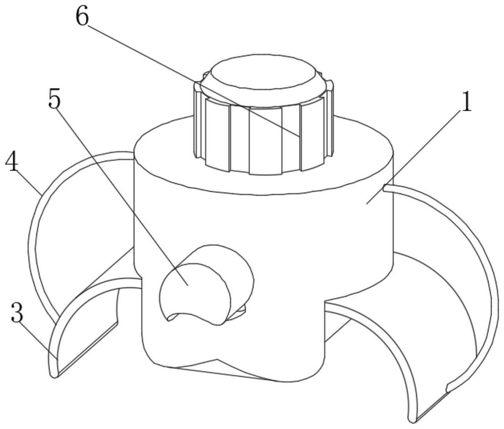
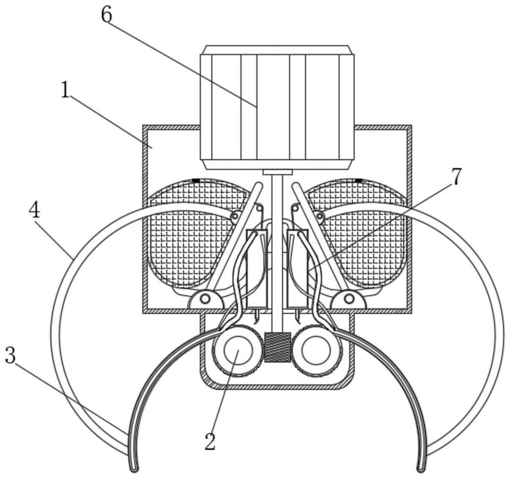
[0022] Such as Figure 1-6 As shown, the present invention provides a technical solution: a fixture for processing cylindrical workpieces, including a casing 1, the lower outer wall of the casing 1 is fixedly connected with a fixed pile 2, and the outer wall of the fixed pile 2 rotates through a bearing The splint head 3 is connected, the outer wall of the splint head 3 is fixedly connected with the pull rod 4, the upper surface of the casing 1 is embedded with a motor 6, the outer wall of the right end of the splint head 3 is provided with a toothed structure, and the lower end of the output rod of the motor 6 passes through the threaded rod and The right end of the splint head 3 is engaged and connected, the outer wall of the casing 1 is provided with a blower mechanism 5 , and the inside of the casing 1 is provided with a transmission mechanism 7 .

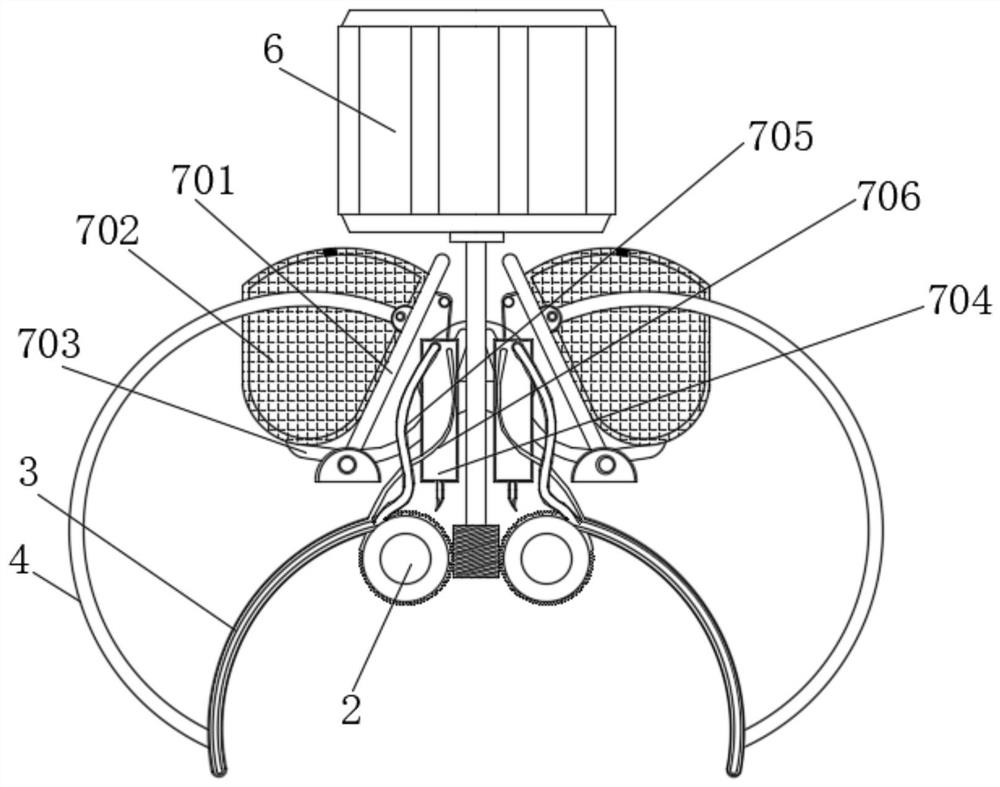
[0023] The transmission mechanism 7 includes a splint 701, an air bag 702, a first air supply pipe 703, a cooling mechanism 7...


PUM


Abstract

The invention relates to the technical field of machining, and discloses a clamp for machining a cylindrical workpiece. The clamp comprises a machine shell, a fixing pile is fixedly connected with the outer wall of the lower side of the machine shell, a clamping plate head is rotatably connected with the outer wall of the fixing pile through a bearing, and a pull rod is fixedly connected with the outer wall of the clamping plate head; a motor is embedded and fixed to the upper surface of the machine shell, and an air supply mechanism is arranged on the outer wall of the machine shell; a transmission mechanism is arranged in the machine shell; during use, the clamping plate head is refilled with air through a second air supply pipe for heat dissipation, and air flows through the interior of a fixing shell to dissipate heat of an oil bag and cooling liquid in the fixing shell; and a mesh plate descends to press an elastic piece to descend to the position of the right side of the clamping plate head and make contact with a tooth-shaped structure on the surface of the clamping plate head, so that tiny vibration is generated, scrap iron on the surface of the clamping plate head is vibrated off, the self-cleaning effect is achieved, and the purpose that the temperature of the clamping head of the clamp can be stable when the high-temperature columnar workpiece is extracted is comprehensively achieved.

Description

technical field [0001] The invention relates to the technical field of machining, in particular to a fixture used for machining cylindrical workpieces. Background technique [0002] During machining, it is often necessary to perform high-temperature treatment on the workpiece. After the high-temperature treatment, the machine needs to take the workpiece out of the high-temperature environment. The chuck of the fixture is repeatedly contacted and cooled with the high-temperature workpiece during long-term work. Changes to its metal properties make the chuck brittle and easy to damage, and the lower temperature of the chuck will cause the temperature of the contact position to drop suddenly when it contacts the workpiece, and then the cylindrical processing is affected by the principle of thermal expansion and cold contraction. The size of the workpiece changes, or its surface color is affected, so it is necessary to solve the problem of stabilizing the temperature of the fixt...

Claims


Application Information

Patent Timeline
Patent Type & Authority Applications(China)
IPC IPC(8): B25J15/00B25J15/02B25J19/00
CPCB25J15/0038B25J15/0206B25J19/0054Y02P70/10
Inventor 唐娟
Owner HUNAN HONGTAI EAST ELECTRICAL & MECHANICAL EQUIP
Why Eureka
Try Eureka