Grouting production line

A production line and grouting technology, which is applied in die-casting molds, ceramic molding workshops, supply devices, etc., can solve the problems of inability to realize high-automatic production, high production costs, and low production efficiency, and solve the problems of low efficiency of manual pouring, structural Simple, quick pour effect

Active Publication Date: 2021-08-13
ZHIXINLONG TECH (GUANGDONG) CO LTD
View PDF6 Cites 1 Cited by
  • Summary
  • Abstract
  • Description
  • Claims
  • Application Information

AI Technical Summary

Problems solved by technology

After stopping for a period of time, pour off the excess mud, and the mud layer close to the inner wall of the plaster model remains in the model; after a period of time, the mud layer naturally shrinks and separates from the model, and the formed rough body can be taken out; In traditional technology, many links in grouting are mostly carried out manually, such as mold removal, grouting, pouring, etc., which still cannot achieve high-automatic production, resulting in high production costs and low production efficiency

Method used


Image

  • Grouting production line
  • Grouting production line
  • Grouting production line

Examples


Embodiment Construction

[0032] The preferred embodiments of the present invention will be described below in conjunction with the accompanying drawings. It should be understood that the preferred embodiments described here are only used to illustrate and explain the present invention, and should not be construed as limiting the present invention.

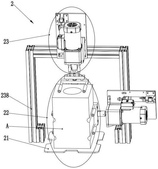
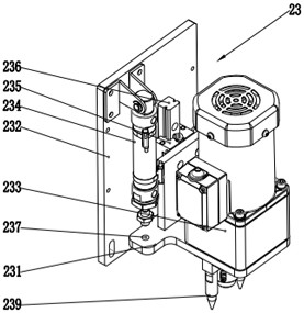
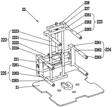
[0033] The application proposes a grouting production line, including a drying device, a grouting device, a slurry suction device, a pouring device, a draining device and a demoulding device; the production sequence of the grouting production line of the present application is demoulding, Mold closing, drying before grouting, grouting, grouting, grouting, draining (the draining process includes draining and drying operation), forming; the grouting production line of this application is a cycle grouting production, so for The molded plaster mold is demolded first, the molded model is taken out, and then the mold is closed to form an empty plaster mold, and t...


PUM


Abstract

The invention discloses a grouting production line. The grouting production line comprises a drying device, a grouting device, a slurry suction device, a slurry pouring device, a slurry draining device and a demolding device. The drying device is used for drying an empty plaster mold before grouting and drying a plaster mold full of slurry during slurry draining; the grouting device is used for grouting the empty plaster mold; the slurry suction device is used for transporting the plaster mold full of the slurry to the slurry pouring device, and the plaster mold full of the slurry completes slurry suction in the transportation process; the slurry pouring device comprises a slurry pouring conveying belt and an overturning assembly which are laid on a slurry pouring rack, and the slurry pouring device is used for overturning the plaster mold full of the slurry after slurry suction; the slurry draining device comprises a conveying mechanism, the conveying mechanism is used for conveying the turned plaster mold full of the slurry to the demolding device, and slurry draining is completed in the transportation process of the plaster mold full of the slurry; and the demolding device is used for executing demolding operation on the plaster mold. Automatic production of all links in the grouting production process is achieved, the production cost is reduced, and the efficiency is improved; and meanwhile, the production line is suitable for automatic production of different manufacturers, different varieties (complex dies) and different processes.

Description

technical field [0001] The invention relates to the technical field of grouting, in particular to a grouting production line. Background technique [0002] In the ceramic industry, daily-use ceramics are usually poured by the grouting molding method. The grouting molding method is relatively simple, that is, the slurry made from the blank is injected into the plaster model. Because the plaster mold has water absorption, it is close to the inner wall of the model. Part of the moisture in the mud is sucked by the porous gypsum to form a mud layer with the same shape as the inner wall of the model on the inner wall of the plaster mold, and this mud layer thickens with time. After stopping for a period of time, pour off the excess mud, and the mud layer close to the inner wall of the plaster model remains in the model; after a period of time, the mud layer naturally shrinks and separates from the model, and the formed rough body can be taken out; In traditional technology, many...

Claims


Application Information

Patent Timeline
Patent Type & Authority Applications(China)
IPC IPC(8): B28B15/00B28B1/26B28B13/02B28B13/06B28B11/24B28B17/00
CPCB28B1/264B28B1/265B28B1/267B28B11/243B28B13/0275B28B13/065B28B15/00B28B17/00
Inventor 郑锋黎光华何辉罗淮黎国雄陈子想陈家劲林建安刘威方长金
Owner ZHIXINLONG TECH (GUANGDONG) CO LTD
Why Eureka
Try Eureka