
Construction method of existing building anti-floating system based on embedded self-propelled anchor

It is a technology of existing buildings and construction methods, which is applied in the direction of construction, infrastructure engineering, and foundation structure repair. It can solve problems such as cracking and water seepage, damage to supporting structures, and compression deformation of building supporting structures to achieve increased bonding. ability, increase the contact area, and ensure the effect of stability

Active Publication Date: 2022-02-08
四川康久美建筑工程有限公司
View PDF5 Cites 0 Cited by
  • Summary
  • Abstract
  • Description
  • Claims
  • Application Information

AI Technical Summary

Problems solved by technology

[0002] When the self-weight of the building and the soil covering the bottom cannot offset the buoyancy generated by the groundwater, the bottom of the existing building is likely to float up due to the action of water pressure, which will cause the supporting structure of the building to be deformed under compression. In severe cases, the supporting structure will be destroyed, affecting the stability of the building; Moreover, since the post-pouring belt, construction joints or cracks formed in the later stage of the raft are weak links, the bottom of the raft is subjected to water pressure for a long time, and the post-pouring belt, construction joints or cracks of the raft further develop, resulting in the raft of the basement of the existing building. Or cracking and water seepage, there is a safety hazard
Moreover, most of the existing anti-floating control methods use the method of drilling pressure relief to release the water pressure of the anti-floating floor of the building, and then apply anchor rods for anti-floating treatment. The distribution of anchor rods is unreasonable. When the subsequent groundwater level rises, Especially in extreme weather such as heavy rain and other environments, the water pressure will always have a pressure effect on the floating floor, and the problem of cracking and leakage of the floating floor has not been solved.

Method used


Image

  • Construction method of existing building anti-floating system based on embedded self-propelled anchor
  • Construction method of existing building anti-floating system based on embedded self-propelled anchor
  • Construction method of existing building anti-floating system based on embedded self-propelled anchor

Examples


Embodiment

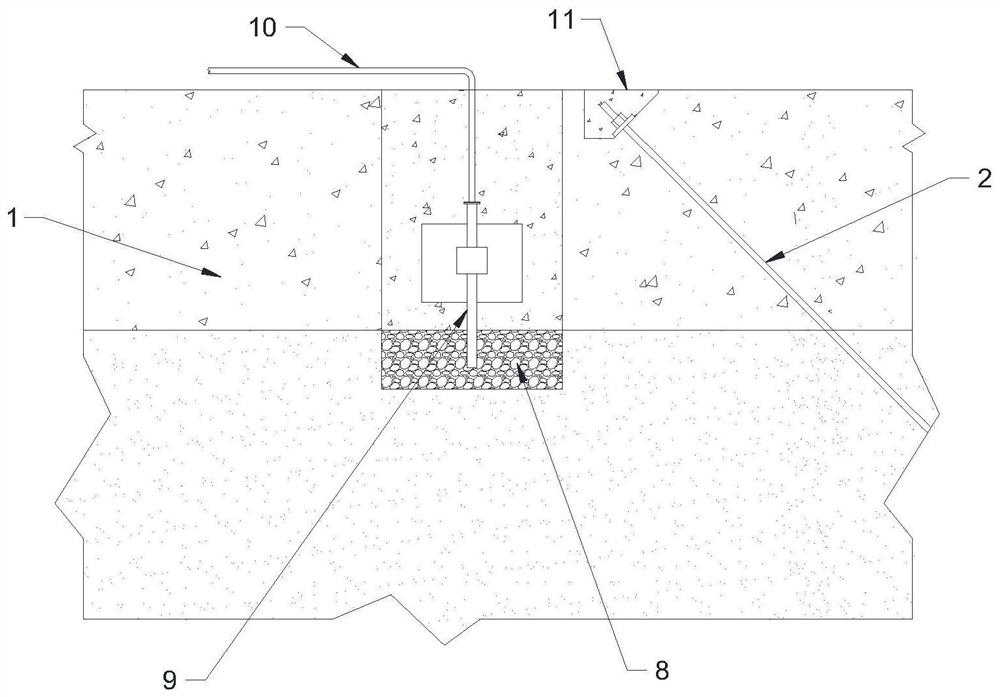
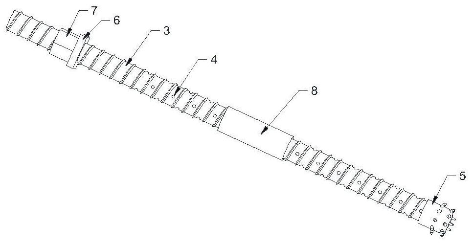
[0035] see Figure 1-6 , the existing building anti-floating system based on embedded self-propelled anchors, including the anchor group applied to the existing building anti-floating floor 1, the anchor group includes a plurality of self-propelled anti-floating anchors 2, each self-propelled The included angle between the advanced anti-floating anchors 2 and the plane where the anti-floating bottom plate 1 is located is 40-75 degrees; the self-advancing anti-floating anchors 2 in the anchor group are arranged opposite to each other in a matrix, and each row of self-advancing anti-floating The floating anchor rods 2 are arranged in parallel, and two adjacent self-propelled anti-floating anchor rods 2 are symmetrically arranged in each row; it also includes a pressure relief pipe 9 inserted on the anti-floating bottom plate 1, and the bottom end of the pressure relief pipe 9 is located at Below the anti-floating floor 1, the other end is connected with the sump outside the buil...


PUM


Abstract

The invention relates to the field of anti-floating technology of existing buildings, and discloses an anti-floating system for existing buildings based on embedded self-advancing anchors and a construction method thereof, including anchor groups applied to anti-floating floors of existing buildings, and anchor groups It includes multiple self-advancing anti-floating anchors installed at 40-75°. The self-advancing anti-floating anchors in the anchor group are arranged in a matrix, which can far meet the design requirements and can resist horizontal disturbances. Reduce the displacement of the building in the horizontal direction; at the same time, the anti-floating management method combining self-propelled anti-floating anchor rods and pressure relief devices can be used to effectively strengthen the anti-floating slab, restore the damaged part of the anti-floating slab, And the filling of voids and gaps under the anti-floating slab; and when designing the distribution density of the self-advancing anti-floating anchor rods, the pressure-reducing effect of the pressure relief device is also fully considered to ensure effective control of the problem of floating existing buildings. It can also reduce the amount of self-propelled anti-floating anchor rods.

Description

technical field [0001] The invention relates to the field of existing building anti-floating technology, in particular to a construction method of an existing building anti-floating system based on embedded self-advancing anchor rods. Background technique [0002] When the self-weight of the building and the soil covering the bottom cannot offset the buoyancy generated by the groundwater, the bottom of the existing building is likely to float up due to the action of water pressure, which will cause the supporting structure of the building to be deformed under compression. In severe cases, the supporting structure will be destroyed, affecting the stability of the building; Moreover, since the post-pouring belt, construction joints or cracks formed in the later stage of the raft are weak links, the bottom of the raft is subjected to water pressure for a long time, and the post-pouring belt, construction joints or cracks of the raft further develop, resulting in the raft of the ...

Claims


Application Information

Patent Timeline
Patent Type & Authority Patents(China)
IPC IPC(8): E02D31/12E02D5/74E02D37/00E02D15/02
CPCE02D31/12E02D5/74E02D37/00E02D15/02E02D2250/003E02D2600/30
Inventor 斯树友何建祥
Owner 四川康久美建筑工程有限公司
Learn More