Method for operating hydraulic drive

A technology of hydraulic drives and hydraulic consumers, applied in the field of computer programs

Pending Publication Date: 2021-08-13
ROBERT BOSCH GMBH
View PDF2 Cites 0 Cited by
  • Summary
  • Abstract
  • Description
  • Claims
  • Application Information

AI Technical Summary

Problems solved by technology

The disadvantage of this solution, however, is that it is necessary to switch the operating type, i.e. it is necessary to switch between force regulation and position regulation
Furthermore, with force regulation via torque, the position is no longer controlled because the position regulator is inactive

Method used


Image

  • Method for operating hydraulic drive
  • Method for operating hydraulic drive
  • Method for operating hydraulic drive

Examples


Embodiment Construction

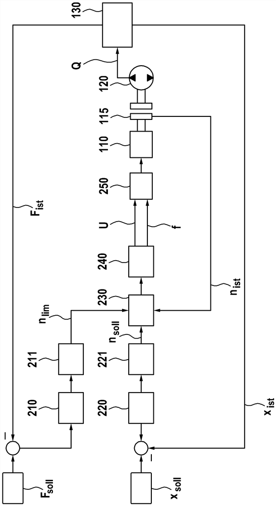
[0031] figure 1 A hydraulic drive 100 in which the method according to the invention can be carried out is shown schematically in FIG. The hydraulic drive 100 currently has a variable-speed electric motor or drive 110 with a stator 111 and a rotor 112 which is connected via a clutch 115 to a hydraulic pump 120 . The hydraulic pump 120 is an axial piston pump embodied as a fixed displacement pump, which has a fixed transport volume in each working gap. The hydraulic pump 120 can be driven variably by the rotational speed by means of the electric motor 110 .

[0032]Furthermore, the hydraulic pump 120 is connected to a hydraulic consumer 130 with positionable elements. The hydraulic consumer 130 is currently designed as a cylinder with a piston as a positionable element, wherein the piston has, for example, a piston rod on both ends. The hydraulic pump 120 is connected to the cylinder at both ends, so that a movement of the piston in both directions is possible depending on t...


PUM


Abstract

The invention relates to a method for operating a hydraulic drive. The drive comprises a hydraulic pump (120) driven by a variable-speed electric motor (110) and a hydraulic consumer (130) connected to the hydraulic pump (120) and comprising positionable elements, wherein the positions of a positionable elements of the hydraulic consumer (130) are adjusted as control variables by means of a position controller (220) through a rotational speed of the electric motor (110), and a pressure on the positionable elements of the hydraulic consumer (130) or a force exerted by the positionable elements of the hydraulic consumer (130) is adjusted by means of a pressure or force controller (210), and a predetermined rotational speed of the electric motor (110) is adjusted by means of a predetermined cycle frequency (f) and / or a predetermined voltage (U) of a magnetic field of a stator of the electric motor (110).

Description

technical field [0001] The invention relates to a method for operating a hydraulic drive with position regulation and pressure or force regulation, as well as a computing unit and a computer program for implementing the method. Background technique [0002] An electrohydraulic shaft is a hydraulic drive with a motor, a hydraulic pump and a hydraulic cylinder, wherein electrical or electronic adjustment of eg the position of the cylinder or the piston of the cylinder is possible. Such electro-hydraulic shafts are used, for example, in so-called deep-drawing presses, injection-molding machines or also in other forming technology machines. [0003] In most cases, separate force-position regulation is provided in such electro-hydraulic shafts, ie force regulation or position regulation takes place, for example, as a function of the operating point. As an alternative to a force regulation, a pressure regulation can also be provided, which is based on the relationship between the...

Claims


Application Information

Patent Timeline
Patent Type & Authority Applications(China)
IPC IPC(8): F15B21/08F15B21/02
CPCF15B21/02F15B21/08F15B2211/6306F15B2211/6336F15B2211/6656B21D24/14B30B15/166F15B7/006F15B21/087F15B2211/20515F15B2211/20538F15B2211/20561F15B2211/27F15B2211/6303F15B2211/6313F15B2211/633F15B2211/6651F15B2211/6653F15B2211/7054G05B19/46
Inventor M·瓦勒R·博内费尔德
Owner ROBERT BOSCH GMBH
Why Eureka
Try Eureka