Annular loop single-mode optical fiber sensor based on a Renner correction model and annular optical fiber loop design method thereof

A fiber optic sensor and loop circuit technology, which is applied in the use of optical devices to transmit the direction of sensing components, optics, instruments, etc., can solve the problems of not considering the influence of deflection, narrow application scenarios, large deviations, etc., and achieve the effect of wide application.

Pending Publication Date: 2021-08-13
苏州清恒智能科技有限公司
View PDF6 Cites 0 Cited by
  • Summary
  • Abstract
  • Description
  • Claims
  • Application Information

AI Technical Summary

Problems solved by technology

[0004] In the prior art, when the annular single-mode optical fiber sensor is designed, it is mostly considered that only by making the annular optical fiber form a displacement in the radial direction during use (see the appendix figure 2 The situation in (b)), thereby changing the use of the laser signal intensity, does not consider that the ring shape of the ring-shaped optical fiber does not change when it is used, only the radius changes (see the appendix figure 2 The case in (a)), which causes the laser signal intensity to change
In addition, the influence of the deflection on the actual results is not considered in the design of the prior art annular single-mode fiber sensor, resulting in a large deviation between the theoretical prediction and the actual test results
Furthermore, the scope of application of the prior art annular single-mode optical fiber sensor is limited to the use in testing the mechanical properties of composite materials, and the application scenarios are relatively narrow

Method used


Image

  • Annular loop single-mode optical fiber sensor based on a Renner correction model and annular optical fiber loop design method thereof
  • Annular loop single-mode optical fiber sensor based on a Renner correction model and annular optical fiber loop design method thereof
  • Annular loop single-mode optical fiber sensor based on a Renner correction model and annular optical fiber loop design method thereof

Examples


Embodiment Construction

[0066] In order to be able to understand the technical means of the present invention more clearly and implement it according to the contents of the description, the specific implementation of the present invention will be further described in detail below in conjunction with the accompanying drawings and examples. The following examples are used to illustrate the present invention, but not to limit the scope of the present invention.

[0067] This specific embodiment records in detail the technical solution claimed in this application, uses a single-mode optical fiber, and describes in detail from the shape design, theoretical calculation and experimental results.

[0068] 1. Shape design

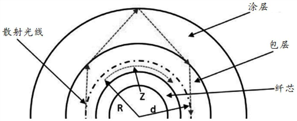
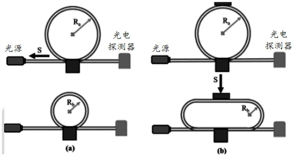
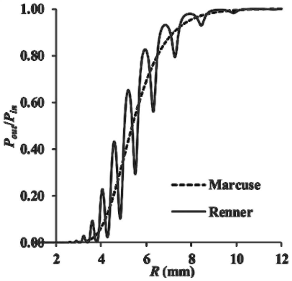
[0069] Mechanical bending of single-mode fiber ( figure 1 ) leads to leakage of the laser light during propagation through the cladding and coating, and reduces the transmission power through the cladding and coating. Therefore, forming sharp bends or loops in the fiber results in a los...


PUM

PropertyMeasurementUnit
Radius valueaaaaaaaaaa

Abstract

The invention discloses an annular loop single-mode optical fiber sensor based on a Renner correction model and an annular optical fiber loop design method thereof, and belongs to the technical field of optical fiber sensor design. According to the design method, a power loss model of an undeformed annular loop optical fiber ring is firstly established, then a deformation equation of a deformed annular loop is established, and then a correlation model of annular loop optical fiber external displacement and optical power attenuation is established on the basis of the deformation equation. And finally, a relative transmitting power loss model of a deformed loop and a non-deformed loop of the annular loop optical fiber loop are established, and a relationship between the shape of the annular optical fiber loop and the loss power is determined. The sensor designed by the design method considers the condition that the shape of the optical fiber ring is not changed and only the size and the shape are changed, and the influence of the deflection of the optical fiber, so that the sensor is wider in application range, large deviation between an actual measurement result and a theoretical prediction result is avoided, and the sensor can be suitable for various application occasions and has wide application prospects. And the measurement range and the precision can be customized.

Description

technical field [0001] The invention relates to an optical fiber sensor and a design method thereof, in particular to a ring loop single-mode optical fiber sensor based on a Renner correction model and a design method thereof, belonging to the technical field of optical fiber sensor design. Background technique [0002] An optical fiber is a flexible, transparent fiber made of extruded glass or plastic, slightly thicker than a human hair, and usually consists of a low-refractive-index transparent core, a transparent cladding material, and an outermost coating. As an optical waveguide, the optical fiber enables total reflection of light in the core. In optical fiber communication, single-mode fiber (SMF) is an optical fiber that directly transmits optical signals in the transverse mode. It operates at a data rate of 100M / s or 1G / s, and the transmission distance can reach at least 5 kilometers. Typically, single-mode fiber is used for long-distance signal transmission. [00...

Claims


Application Information

Patent Timeline
IPC IPC(8): G01D5/32G02B27/00
CPCG01D5/32G02B27/0012
Inventor 杨弋
Owner 苏州清恒智能科技有限公司
Why Eureka
Try Eureka