Method for generating 3D printing supporting structure

A support structure and 3D printing technology, applied in the field of 3D printing, can solve the problems of wasting processing materials and processing time, workpiece damage, and difficult separation of workpieces without damage, and achieve the effect of saving processing materials and processing time and reducing contact area

Active Publication Date: 2021-08-13
CHANGCHUN INST OF OPTICS FINE MECHANICS & PHYSICS CHINESE ACAD OF SCI
View PDF13 Cites 0 Cited by
  • Summary
  • Abstract
  • Description
  • Claims
  • Application Information

AI Technical Summary

Problems solved by technology

The disadvantage is that it not only wastes the processing materials and processing time, but also it is difficult to separate the support structure from the workpiece in the post-processing without damage, resulting in the damage of the workpiece

Method used


Image

  • Method for generating 3D printing supporting structure
  • Method for generating 3D printing supporting structure
  • Method for generating 3D printing supporting structure

Examples


Embodiment Construction

[0038] Embodiments of the present invention will be further described in detail below in conjunction with the accompanying drawings and examples. It should be noted that, in the case of no conflict, the embodiments of the present invention and the features in the embodiments can be combined with each other. Based on the embodiments of the present invention, all other embodiments obtained by persons of ordinary skill in the art without creative efforts fall within the protection scope of the present invention.

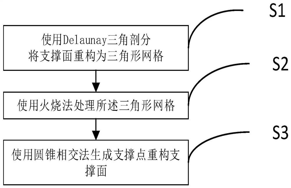
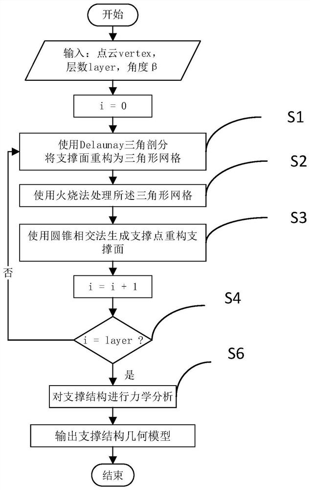
[0039] figure 1 It shows a first schematic flow chart of a method for generating a 3D printing support structure according to an embodiment of the present invention, figure 2 It shows a second schematic flow chart of the method for generating a 3D printing support structure according to an embodiment of the present invention. The embodiment provides a method for generating a 3D printing support structure, which includes the following steps:

[0040] S1, using the Del...


PUM


Abstract

The invention relates to a method for generating a 3D printing support structure. The method comprises the following steps: reconstructing a support surface into a triangular mesh by using a Delaunay triangle subdivision method; performing classification extraction on the triangular grids by using a burning method to generate a unit set; and processing the unit set by using a cone intersection method to generate supporting points to reconstruct the supporting surface. Optimization of the supporting structure can be further realized. According to the generated supporting structure, the contact area between the supporting structure and the printing model is reduced, rapid separation of the supporting structure and the model is achieved, and the printing model is not prone to being damaged.

Description

technical field [0001] The invention relates to the field of 3D printing, in particular to a method for generating a 3D printing support structure. Background technique [0002] 3D printing is a rapid prototyping technology. The 3D printer is equipped with different printing materials such as metal, ceramics, plastics, sand, etc., and the printing materials are superimposed layer by layer through control to form a real object. The main process of the commonly used 3D printing technology is to melt the filamentous hot-melt material, and spray the melted material through a fine nozzle. After a layer of material is deposited, the workbench is lowered according to the set program or the nozzle is raised by one level of thickness, and then the above steps are repeated until the workpiece is manufactured. That is, by printing from the bottom layer. Therefore, for workpieces with suspended structures, they cannot be printed if there is no support structure underneath. [0003] A...

Claims


Application Information

Patent Timeline
Patent Type & Authority Applications(China)
IPC IPC(8): G06F30/10G06F30/27G06T17/20B29C64/386B33Y50/00B22F3/115B33Y80/00B22F10/80G06F113/10
CPCG06F30/10G06F30/27G06T17/205B29C64/386B33Y50/00B22F3/115B33Y80/00G06F2113/10Y02P10/25
Inventor 王冲左同星刘震宇宫鹏王强龙韩海涛余毅
Owner CHANGCHUN INST OF OPTICS FINE MECHANICS & PHYSICS CHINESE ACAD OF SCI
Why Eureka
Try Eureka