Stator glue pouring tool and stator glue pouring method based on same

A stator and glue filling technology, which is applied in the manufacture of stator/rotor bodies, electromechanical devices, cooling/ventilation devices, etc., can solve the problems of reduced service life of the motor, unsatisfactory heat dissipation effect, and aging of the coil insulation layer, so as to reduce service failures The effect of shortening the glue filling process cycle and prolonging the service life

Pending Publication Date: 2021-08-13
苏州精力电气有限公司
View PDF0 Cites 5 Cited by
  • Summary
  • Abstract
  • Description
  • Claims
  • Application Information

AI Technical Summary

Problems solved by technology

[0002] The stator of industrial explosion-proof motors and squirrel-cage motors generates a lot of heat. The traditional heat dissipation mode is to transfer heat to the motor shell through heat radiation, and then dissipate heat to the external space through the motor shell. This heat dissipation method is due to The heat transfer efficiency is low, so the heat dissipation effect is not ideal, which often leads to the overheating of the stator coil, the rapid aging of the coil insulation layer, and the reduction of the service life of the motor

Method used


Image

  • Stator glue pouring tool and stator glue pouring method based on same
  • Stator glue pouring tool and stator glue pouring method based on same

Examples


Embodiment 1

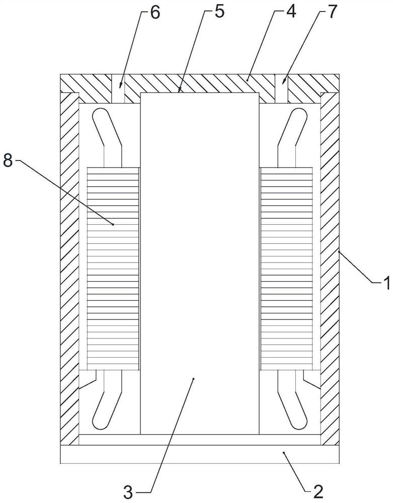
[0032] Such as figure 1 The stator glue filling tool shown includes a lower sealing plate 2 that is closed and docked with one end of the motor housing 1, a mold column 3 that is vertically connected to the lower sealing plate 2 and plugged into the center of the motor housing 1, and is connected to the motor housing 1. The other end of the housing 1 is closed to the butted upper sealing plate 4, and the upper sealing plate 4 is provided with a groove 5 matching with the mold column 3, and the mold column 5 is inserted into the groove 5 on the upper sealing plate 4, and the upper sealing plate 4 The sealing plate 4 is additionally provided with an upper glue hole 6 and an exhaust hole 7 .

[0033] In this embodiment, the outer diameter of the mold column 3 is preferably larger than the outer diameter of the rotor and smaller than the inner diameter of the stator 8, so that a layer of glue can be formed on the inner hole wall of the stator to improve the anti-corrosion performa...

Embodiment 2

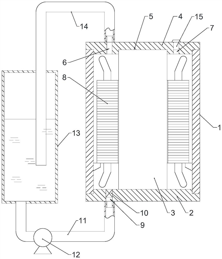
[0042] Embodiment 2: as figure 1 The stator glue filling tool shown includes a lower sealing plate 2 that is closed and docked with one end of the motor housing 1, a mold column 3 that is vertically connected to the lower sealing plate 2 and plugged into the center of the motor housing 1, and is connected to the motor housing 1. The other end of the housing 1 is closed to the butted upper sealing plate 4, and the upper sealing plate 4 is provided with a groove 5 matching with the mold column 3, and the mold column 5 is inserted into the groove 5 on the upper sealing plate 4, and the upper sealing plate 4 The sealing plate 4 is additionally provided with an upper glue hole 6 and an exhaust hole 7 .

[0043] The lower sealing plate 2 is provided with a lower glue hole 9, and a leak-proof check valve 10 can be arranged in the lower glue hole 9. A pump hose 11 is detachably connected to the lower glue hole 9, and the pump hose 11 passes through the pump. The body 12 communicates ...


PUM


Abstract

The invention relates to a stator glue pouring tool and a stator glue pouring method based on the same. The stator glue pouring tool comprises a lower sealing plate in sealed butt joint with one end of a motor shell, a mold column vertically connected to the lower sealing plate and inserted into the center of the motor shell, and an upper sealing plate in sealed butt joint with the other end of the motor shell, wherein a groove matched with the mold column is formed in the upper sealing plate, the mold column is inserted into the groove in the upper sealing plate, and an upper glue pouring hole and an exhaust hole are additionally formed in the upper sealing plate. The stator glue pouring tool can perform integral glue pouring on the motor stator and the motor shell, so that the space between the stator and the motor shell is filled with the pouring sealant, the heat conduction efficiency between the stator and the motor shell is improved, and the temperature of a winding is reduced.

Description

technical field [0001] The invention relates to a stator glue filling tool and a stator glue filling method based on the glue filling tool. Background technique [0002] The stator of industrial explosion-proof motors and squirrel-cage motors generates a lot of heat. The traditional heat dissipation mode is to transfer heat to the motor shell through heat radiation, and then dissipate heat to the external space through the motor shell. This heat dissipation method is due to The heat transfer efficiency is low, so the heat dissipation effect is not ideal, which often leads to the overheating of the stator coil, the rapid aging of the coil insulation layer, and the reduction of the service life of the motor. Contents of the invention [0003] The first technical problem to be solved by the present invention is: to provide a stator glue filling tool, which can carry out integral glue filling on the motor stator and the motor casing, so that the gap between the stator and the ...

Claims


Application Information

Patent Timeline
Patent Type & Authority Applications(China)
IPC IPC(8): H02K15/02H02K9/22H02K5/24
CPCH02K5/24H02K9/22H02K15/02
Inventor 关暘梁太海吴永干常新建牟廷超朱颂恩
Owner 苏州精力电气有限公司
Why Eureka
Try Eureka