Machining method for spare part of punch pin

A processing method and technology for spare parts, applied in the direction of metal processing equipment, manufacturing tools, grinding workpiece supports, etc., can solve the problems of long processing cycle, slow grinding progress, low efficiency, etc., and achieve good forming effect, simple processing, and high efficiency Effect

Pending Publication Date: 2021-08-17
WUXI MICRO RES
View PDF8 Cites 1 Cited by
  • Summary
  • Abstract
  • Description
  • Claims
  • Application Information

AI Technical Summary

Problems solved by technology

[0002] like image 3 Shown is a schematic diagram of the shape of a punch. The punch is characterized by many changes in radial dimensions and a smooth transition through the arc surface. Therefore, the traditional method of machining by tool turning is difficult to apply and cannot meet the process requirements.
At present, for this situation, slow wire processing or optical curve grinding are mainly used. Slow wire processing is limited by the clamping method and cannot be processed at one time. It must be clamped again in the middle, which is inefficient and the molding quality is not as good as the grinding effect. ; while the optical curve grinding process has high molding quality and dimensional accuracy, but the grinding progress is slow. When processing this part, it is necessary to process the upper, lower, left, and right sides one by one. The process requires repeated turning and positioning, and the processing cycle is long.

Method used


Image

  • Machining method for spare part of punch pin
  • Machining method for spare part of punch pin
  • Machining method for spare part of punch pin

Examples


Embodiment Construction

[0021] The technical solutions of the present invention will be further described below in conjunction with the accompanying drawings and through specific implementation methods.

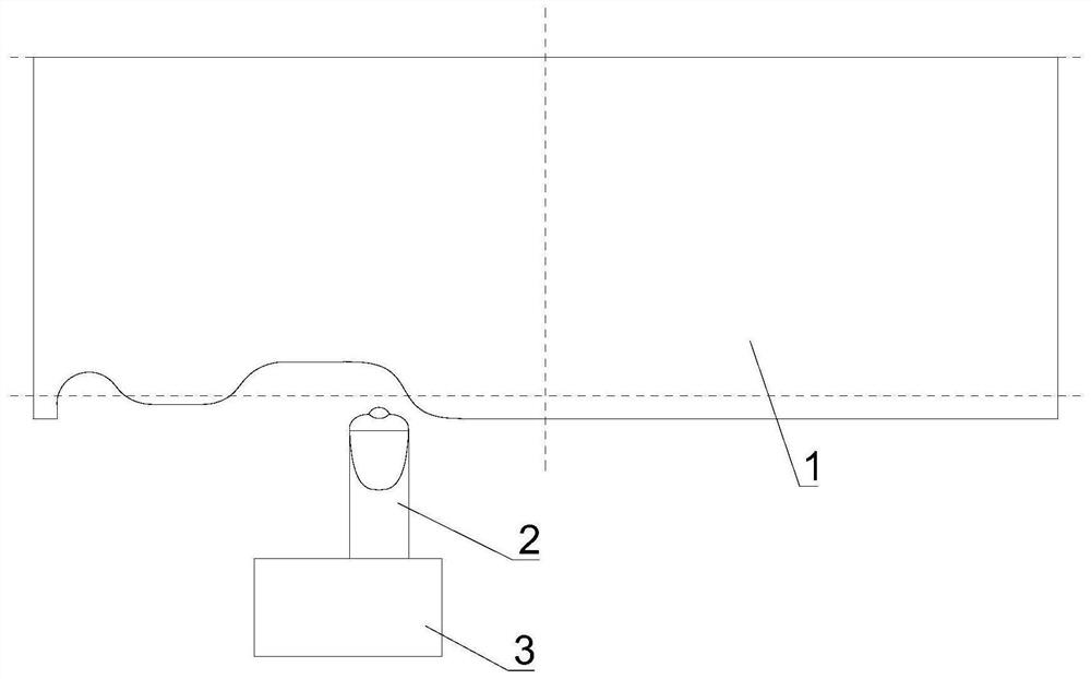
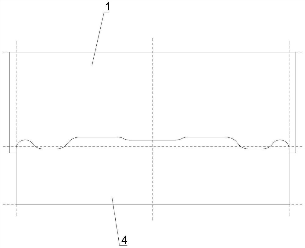
[0022] see figure 1 with 2 As shown, the present embodiment provides a processing method for punch spare parts, comprising steps:

[0023] Step 1: Obtain the required grinding wheel profile according to the graphics of the parts to be processed.

[0024] The graphics of the parts are drawn by computer software, the corresponding coordinates of the track points of the grinding wheel profile are measured, and the moving track of the diamond pen 2 is reasonably designed. It should be noted that when calculating the point coordinates, the overcut of the grinding wheel should be considered, otherwise it is easy to produce unqualified products during processing.

[0025] Step 2: Use diamond pen 2 to trim the forming grinding wheel 1 of the target profile.

[0026] Diamond pen 2 is installed on the fi...


PUM


Abstract

The invention discloses a machining method for a spare part of a punch pin. The machining method for the spare part of the punch pin comprises the following steps: obtaining the molded surface of a required grinding wheel according to a pattern of the part to be processed; trimming the forming grinding wheel with the target molded surface through a diamond pen; and directly grinding a part block into a target shape by the forming grinding wheel. According to the machining method for the spare part of the punch pin, the forming grinding wheel is adopted for carrying out grinding treatment on the part block, the desired shape is directly obtained, and compared with a point machining mode of slow wire feeding machining and optical curve grinding machining, the linear machining mode is high in efficiency, and simple in machining and good in forming effect especially for an arc surface and a forming surface with multiple radial size changes; and in addition, even if the grinding wheel needs to be trimmed, the whole machining period still has the advantages, and the machining method for the spare part of the punch pin is particularly suitable for machining and production for batch parts.

Description

technical field [0001] The invention relates to the technical field of machining, in particular to a processing method for punch spare parts. Background technique [0002] Such as image 3 Shown is a schematic diagram of the shape of a punch. The punch is characterized by many changes in radial dimensions and a smooth transition through the arc surface. Therefore, the traditional machining method by tool turning is difficult to apply and cannot meet the process requirements. At present, for this situation, slow wire processing or optical curve grinding are mainly used. Slow wire processing is limited by the clamping method and cannot be processed at one time. It must be clamped again in the middle, which is inefficient and the molding quality is not as good as the grinding effect. ; while the optical curve grinding process has high molding quality and dimensional accuracy, but the grinding progress is slow. When processing this part, it is necessary to process the upper, low...

Claims


Application Information

Patent Timeline
Patent Type & Authority Applications(China)
IPC IPC(8): B24B19/20B24B53/06B24B41/06
CPCB24B19/20B24B53/06B24B41/06
Inventor 李民卢其欢陈亮陈小龙姚新飞
Owner WUXI MICRO RES
Why Eureka
Try Eureka