
High-quality battery aluminum foil slitting device

A high-quality, aluminum foil technology, applied in metal processing and other directions, can solve problems affecting processing accuracy, blade hardness loss, lung tissue fibrosis, etc., and achieve high cutting efficiency

Pending Publication Date: 2021-08-17
安徽力幕新材料科技有限公司
View PDF8 Cites 2 Cited by
  • Summary
  • Abstract
  • Description
  • Claims
  • Application Information

AI Technical Summary

Problems solved by technology

[0002] Usually, the high-quality battery industry uses rolled aluminum foil as the positive electrode collector. However, when the aluminum foil coil with a larger width is cut into smaller aluminum foil coils according to requirements, there will be burrs and warping on both sides. Edges are generated, which seriously affects the subsequent processing accuracy. Aluminum foil slitting is carried out in a tearing manner, and slitting aluminum powder is inevitable during the slitting process. On the one hand, during the slitting process, the blade running at high speed will rub against and generate heat , so that the blade is accompanied by high temperature, the blade with too high temperature will be stuck to the blade by aluminum powder, and the blade will lose its sharpness. The slit aluminum foil has serious quality problems such as edge warping, curling, and ruffles. At the same time, the aluminum powder falls to the surface of the material and will form a crater after winding, and the aluminum powder that is too light will form aluminum dust and float in the air. , staff breathing air containing aluminum for a long time will cause fibrosis of lung tissue and aluminum pneumoconiosis, which seriously affects the health of staff. Therefore, the present invention provides a high-quality battery aluminum foil cutting device for solving above question

Method used


Image

  • High-quality battery aluminum foil slitting device
  • High-quality battery aluminum foil slitting device
  • High-quality battery aluminum foil slitting device

Examples


Embodiment Construction

[0026] Materials, methods and instruments used in the following examples, without special instructions, are conventional materials, methods and instruments in the art, and those of ordinary skill in the art can obtain them through commercial channels.

[0027] In the following description of the present invention, it should be noted that the terms "center", "longitudinal", "transverse", "upper", "lower", "front", "rear", "left", "right", The orientation or positional relationship indicated by "top", "bottom", "inner", "outer" and "vertical" are based on the orientation or positional relationship shown in the drawings, and are only for the convenience of describing the present invention and simplifying the description. It is not intended to indicate or imply that the referred device or element must have a particular orientation, be constructed in a particular orientation, and operate in a particular orientation, and thus should not be construed as limiting the invention.

[002...


PUM


Abstract

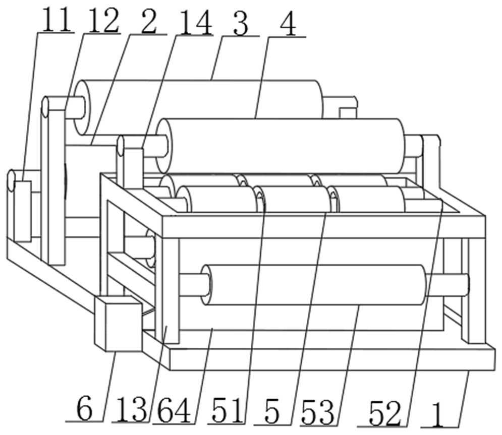
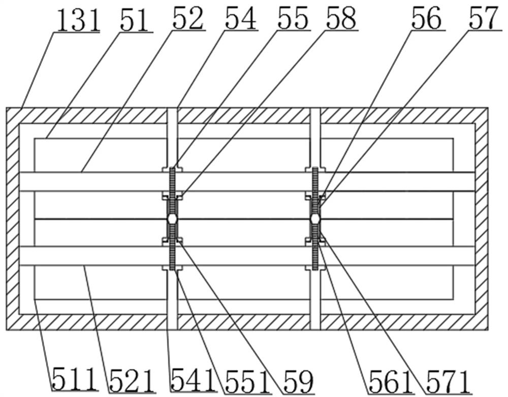
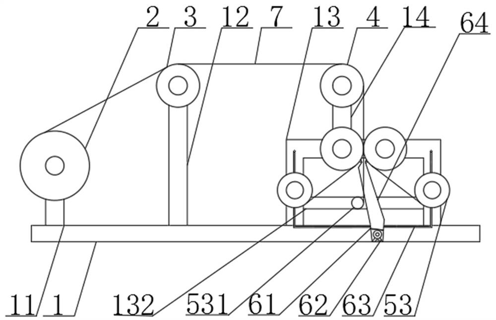
The invention belongs to the technical field of aluminum foil production, and particularly relates to a high-quality battery aluminum foil slitting device, which comprises a base; a material distributing roller is installed at one end of the top of the base; aluminum foil is wound on the outer wall of the material distributing roller; a first material guiding roller is installed at the top of the base, and a slitting mechanism is installed at the other end of the top of the base; a second material guiding roller is installed above the slitting mechanism through a fourth supporting column; and a negative pressure collecting box is installed on the side face of the base. The aluminum foil is slit into the specified width through the slitting mechanism, the slitting efficiency is high, the quality problems of edge warping, rough warping and the like are solved, aluminum powder falling in the slitting process is collected through the arranged negative pressure collecting box, and the phenomenon that pressing pits are formed after the aluminum powder falls on the material surface and is rolled is avoided, and meanwhile the phenomenon that too light aluminum powder forms aluminum dust and floats in the air, and the body health of workers is affected is avoided.

Description

technical field [0001] The invention belongs to the technical field of aluminum foil production, and in particular relates to an aluminum foil cutting device suitable for high-quality batteries. Background technique [0002] Usually, the high-quality battery industry uses rolled aluminum foil as the positive electrode collector. However, when the aluminum foil coil with a larger width is cut into smaller aluminum foil coils according to requirements, there will be burrs and warping on both sides. Edges are generated, which seriously affects the subsequent processing accuracy. Aluminum foil slitting is carried out in a tearing manner, and slitting aluminum powder is inevitable during the slitting process. On the one hand, during the slitting process, the blade running at high speed will rub against and generate heat , so that the blade is accompanied by high temperature, the blade with too high temperature will be stuck to the blade by aluminum powder, and the blade will lose...

Claims


Application Information

Patent Timeline
Patent Type & Authority Applications(China)
IPC IPC(8): B26D1/15B26D7/06B26D7/08B26D7/18B26D7/28B26D7/32
CPCB26D1/15B26D7/06B26D7/28B26D7/32B26D7/08B26D7/088B26D7/1854
Inventor 梁稳杨繁
Owner 安徽力幕新材料科技有限公司
Learn More