
Optimization design method for asymmetric leading edge structure of turbine blade based on uniform design

A turbine blade, uniform design technology, applied in design optimization/simulation, special data processing applications, instruments, etc., can solve problems such as heavy workload, unbalanced calculation sample screening, and failure to consider the impact of flow control effects.

Active Publication Date: 2021-08-17
NORTHWESTERN POLYTECHNICAL UNIV
View PDF4 Cites 0 Cited by
  • Summary
  • Abstract
  • Description
  • Claims
  • Application Information

AI Technical Summary

Problems solved by technology

Although the control variable trial and error method is used to optimize the design parameters of the leading edge structure to a certain extent, the optimization process relies on the regularity of the cascade loss after modifying a single design parameter, and does not consider the coupling of different design parameter changes. The effect of the effect on the flow control effect, the screening of the calculation sample is not balanced and not comprehensive
But if you calculate one by one according to the permutation and combination, n design variables, each variable has m cases, you need to calculate at least m n As a result, the number of samples increases exponentially, and the workload is too huge

Method used


Image

  • Optimization design method for asymmetric leading edge structure of turbine blade based on uniform design
  • Optimization design method for asymmetric leading edge structure of turbine blade based on uniform design
  • Optimization design method for asymmetric leading edge structure of turbine blade based on uniform design

Examples


Embodiment Construction

[0065] The embodiments described below with reference to the accompanying drawings are exemplary, and are intended to explain the present invention and should not be construed as limiting the present invention.

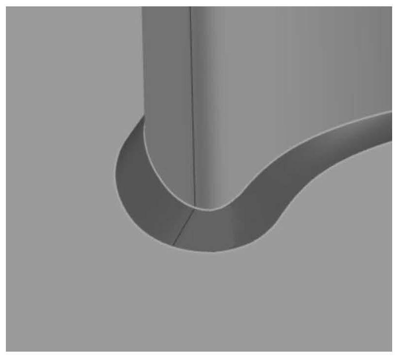
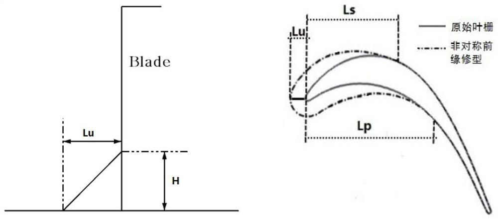
[0066] An optimal design method for the asymmetric leading edge structure of a turbine blade based on a uniform design proposed by the present invention, the specific implementation process of which can be summarized as follows: modeling→optimization→solving for optimization. That is, for the specific turbine blade cascade, the asymmetric leading edge structure is first modeled, as shown in Figure (1), then the design parameters are optimized based on uniform design, and finally the test sample is numerically calculated to find the optimal result. Specifically:

[0067] Step 1: Mathematical modeling of the asymmetric leading edge structure of the turbine blade;

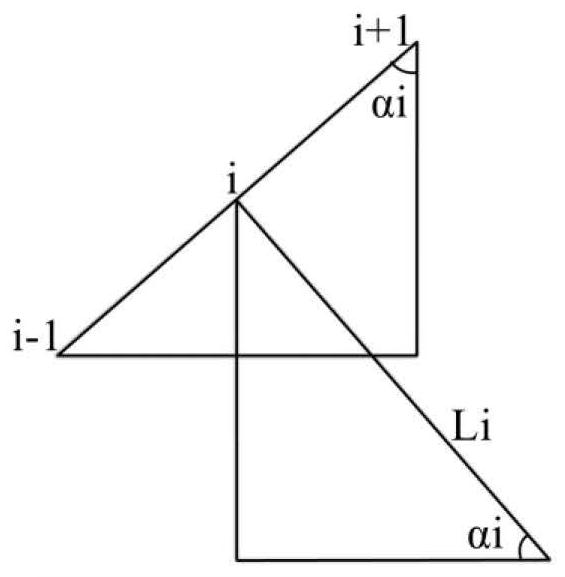
[0068] By discretizing the airfoil near the end wall of the turbine blade, the suction pressure surface o...


PUM


Abstract

The invention discloses an optimal design method for an asymmetric front edge structure of a turbine blade based on uniform design, and belongs to the field of gas turbine engines. Firstly, mathematical modeling is carried out, then a control variable is adopted to carry out trial calculation and reduction on a design parameter change range, finally, uniform design is adopted to optimize asymmetric leading edge structure design parameters in the reduction range, a calculation sample is generated, numerical calculation is carried out, and a result with the minimum total pressure loss is obtained. According to the method, it is guaranteed that design parameters of the asymmetric leading edge have the statistical characteristic of uniform distribution, and each level of each factor can be subjected to one time and only one time of test, so that the coupling effect between parameter changes can be weakened, and an ideal optimization result can be obtained through the least number of tests. The control effect of the result obtained through the method on the total pressure loss is far greater than the control effect of the result obtained through simple control variable trial and error calculation.

Description

technical field [0001] The invention belongs to the field of gas turbine engines, and in particular relates to an optimization design method based on a uniformly designed asymmetrical leading edge structure of a turbine blade. Background technique [0002] There is a very complex secondary flow vortex system in the turbine end area, and the secondary flow loss has an important impact on the turbine efficiency and even the performance of the entire engine. The secondary flow loss caused by the secondary flow eddy system is the main component of the end zone loss. Therefore, from the perspective of weakening / suppressing the vortex, domestic and foreign scholars have proposed many methods to control the secondary flow in the end zone. As a simple and low-cost control method, leading edge trimming has shown broad application prospects in turbine end-zone flow control. [0003] Zess et al. first applied a band-like structure to the leading edge of the blade root of a turbine gu...

Claims


Application Information

Patent Timeline
IPC IPC(8): G06F30/17G06F30/28G06F119/14
CPCG06F30/17G06F30/28G06F2119/14
Inventor 吴艳辉郭鑫范鑫周小兵
Owner NORTHWESTERN POLYTECHNICAL UNIV
Learn More