an optical module

An optical module and power pin technology, which is applied in the field of optical communication, can solve the problems that the power signal cannot meet the requirements of higher-speed optical modules, the power signal flow capacity is limited, and the circuit board space is limited, so as to ensure the power signal flow. Flow capability, small parasitics and crosstalk, and the effect of meeting power requirements

Active Publication Date: 2022-06-17
HISENSE BROADBAND MULTIMEDIA TECH
View PDF9 Cites 0 Cited by
  • Summary
  • Abstract
  • Description
  • Claims
  • Application Information

AI Technical Summary

Problems solved by technology

[0003] In the existing optical module, due to the limited space on the circuit board, the power signal flow capacity corresponding to the gold finger is limited; and with the increase of the transmission rate of the optical module, the corresponding power consumption is getting larger and larger. The layout of the power signal cannot meet the requirements of higher rate optical modules

Method used


Image

  • an optical module
  • an optical module
  • an optical module

Examples


Embodiment Construction

[0040] In order to make those skilled in the art better understand the technical solutions in the present application, the technical solutions in the embodiments of the present application will be clearly and completely described below with reference to the accompanying drawings in the embodiments of the present application. Obviously, the described The embodiments are only a part of the embodiments of the present application, but not all of the embodiments. Based on the embodiments in the present application, all other embodiments obtained by those of ordinary skill in the art without creative work shall fall within the protection scope of the present application.

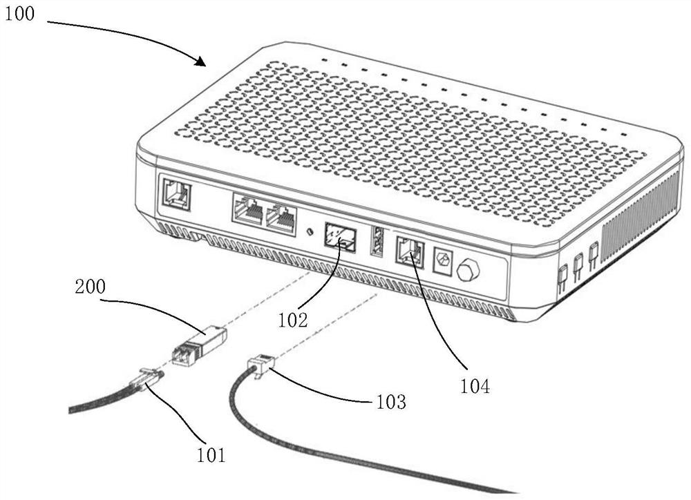
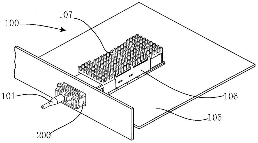
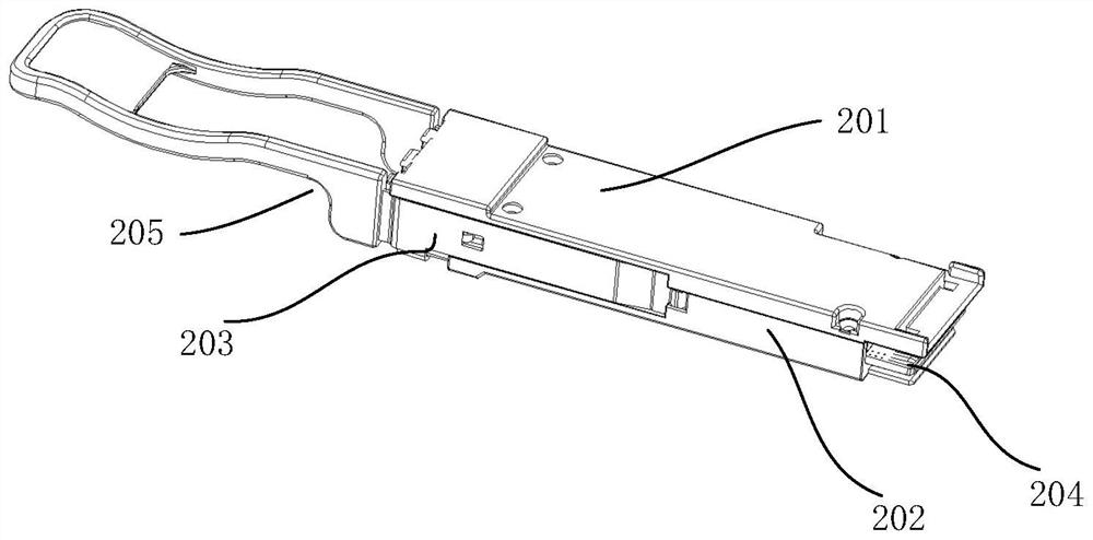
[0041] One of the core links of optical communication is the mutual conversion of optical and electrical signals. Optical communication uses optical signals that carry information to transmit in information transmission equipment such as optical fibers / optical waveguides. The passive transmission characteristics o...


PUM


Abstract

An optical module provided by the present application includes a circuit board, the circuit board includes an upper surface, an intermediate layer and a lower surface, wherein the upper surface is provided with an upper power supply structure, and the upper power supply structure includes a first power supply pin and a first power supply pin connection end , the middle layer is provided with a power supply metal layer on the projection area of ​​the upper power supply structure, and the lower surface is provided with a lower power supply structure, and the lower power supply structure includes a second power supply pin and a second power supply pin connection terminal, wherein, on the one hand, the first The area design of the first power supply pin or the second power supply pin is larger than that of other pins, which can increase the flow capacity of the power supply signal; on the other hand, the area of ​​the middle power supply metal layer is larger than the area of ​​the upper power supply structure. At the same time, it is also larger than the area of ​​the lower power supply structure, that is, the area of ​​the power metal layer in the middle layer is designed to be larger, which can ensure the power signal flow capability, and the parasitic parameters and crosstalk are smaller, thereby meeting the power consumption of higher-speed optical modules. need.

Description

technical field [0001] The present application relates to the technical field of optical communication, and in particular, to an optical module. Background technique [0002] With the development of new business and application models such as cloud computing, mobile Internet, and video, the development and progress of optical communication technology has become more and more important. In the optical communication technology, the optical module is a tool to realize the mutual conversion of photoelectric signals, and it is one of the key components in the optical communication equipment; in the use of the optical module, the optical module is connected with the host computer such as the optical network terminal through the golden finger. The power supply enters the circuit board through the golden finger, and the power supply signal layout design on the circuit board is used to supply power to each chip to ensure the normal operation of the optical module. [0003] In the ex...

Claims


Application Information

Patent Timeline
Patent Type & Authority Patents(China)
IPC IPC(8): H04B10/40
CPCH04B10/40
Inventor 郑龙樊凤梅方浩杨思更
Owner HISENSE BROADBAND MULTIMEDIA TECH
Why Eureka
Try Eureka