A conveying shot peening device for scarifier
A technology of shot blasting device and ripper, which is applied in the field of construction machinery parts processing, can solve the problems of large shaking of conveying ripper, on-site chaos, and large area, so as to reduce the process of intermediate hoisting and transfer, facilitate hoisting and connection, and improve the safety effect
- Summary
- Abstract
- Description
- Claims
- Application Information
AI Technical Summary
Problems solved by technology
Method used
Image
Examples
Embodiment
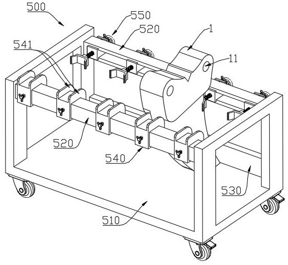
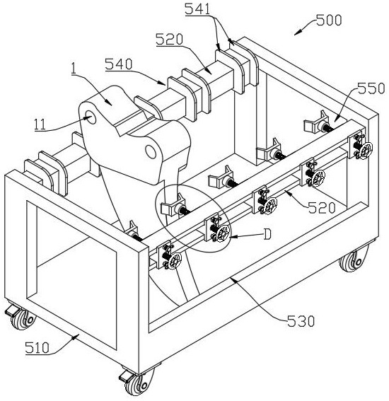
[0051] Such as Figure 1 to Figure 9 As shown, a conveying shot blasting device for a ripper includes: a shot blasting device 100 , a horizontal conveying mechanism 200 , a longitudinal conveying mechanism 300 , a hook assembly 400 and a material frame 500 . The structure of the applied ripper 1 of the application is as Figure 7 As shown in , the ripper 1 has a pair of earholes 11. When the ripper 1 is used, the earholes 11 are used to hinge with the arm of the excavator or bulldozer. Because the finishing process and the installation of the bushing will be carried out later, this part does not need Carry out hardening treatment, the position that needs hardening of ripper 1 is mainly the hook portion of lower segment.
[0052] Specifically, the inside of the shot blasting device 100 has an accommodating cavity for accommodating the ripper 1, and nozzles are provided along the circumference of the accommodating cavity for spraying emery at high speed to the ripper 1, so as t...
specific Embodiment approach
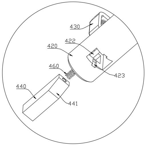
[0071] When hoisting scarifier 1, if figure 1 As shown, the vertical conveying mechanism 300 is moved along the transverse conveying mechanism 200 to the top of the feed side material frame 500, and then the lifting plate 310 and the hook assembly 400 are driven downward by the endless chain 330, so that the boom 420 is aligned with the ear hole 11; Move the material frame 500 in the direction of the suspender 420 so that the suspender 420 is inserted into the ear hole 11. When inserted, the stopper 430 is pushed by the end face of the ear hole 11 and will shrink to the inside of the suspender 420, so that the suspender 420 passes through the ear hole 11; After the boom 420 passes through the ear hole 1, the stopper 430 protrudes from the outer circumference of the boom 420 to fix the ripper 1; Make the hook assembly 400 and the ripper 1 all be located in the shot blasting device 100, then, as Figure 4 The sealing plate 110 is closed as shown, and the shot blasting work is s...
PUM
 Abstract
Description
Claims
Application Information
 - R&D
- Intellectual Property
- Life Sciences
- Materials
- Tech Scout
- Unparalleled Data Quality
- Higher Quality Content
- 60% Fewer Hallucinations
Browse by: Latest US Patents, China's latest patents, Technical Efficacy Thesaurus, Application Domain, Technology Topic, Popular Technical Reports.
© 2025 PatSnap. All rights reserved.Legal|Privacy policy|Modern Slavery Act Transparency Statement|Sitemap|About US| Contact US: help@patsnap.com


