Conveying type shot blasting device for scarifier

A technology of shot blasting device and ripper, applied in the field of construction machinery parts processing, can solve the problems of on-site chaos, hidden safety hazards, low efficiency, etc.

Active Publication Date: 2021-08-20
成都中挖智能科技有限公司
View PDF11 Cites 3 Cited by
  • Summary
  • Abstract
  • Description
  • Claims
  • Application Information

AI Technical Summary

Problems solved by technology

[0004] (1) Since the position of the ripper remains fixed during shot blasting, and in order to facilitate the transportation of the ripper, the injection pipes for shot blasting are usually set on both sides of the conveying direction, and only the two end faces of the ripper can be effectively sprayed. shot treatment, but the arc-shaped structure of the ripper lacks special injection pipes on the inner and outer walls, and only relies on the injection pipes on both sides to contact the inner and outer walls at an oblique angle, resulting in the inner and outer walls. The shot peening effect is poor and the hardness is relatively low
[0005] (2) Most of the existing devices use common U-shaped hooks to hang the ripper, which causes the transport ripper to shake greatly, which has a negative impact on the service life of the conveying and hoisting structure, and therefore has a large safety hazard
When hoisting and removing the ripper, it is necessary to use external lifting devices, such as cranes, lifting hoists and other devices to lift the ripper and transfer it to the hook of the conveyor line. The operation is cumbersome and the efficiency is low. There is a great security risk
In addition, if the ripper adopts a flat laying method, it will occupy a large area, resulting in a very messy site and inconvenient storage.

Method used


Image

  • Conveying type shot blasting device for scarifier
  • Conveying type shot blasting device for scarifier
  • Conveying type shot blasting device for scarifier

Examples


Embodiment

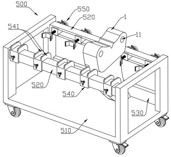
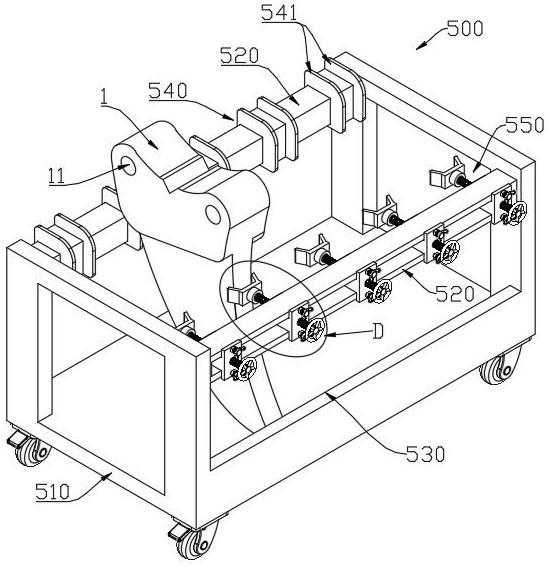
[0051] Such as Figure 1 to Figure 9 As shown, a conveying shot blasting device for a ripper includes: a shot blasting device 100 , a horizontal conveying mechanism 200 , a longitudinal conveying mechanism 300 , a hook assembly 400 and a material frame 500 . The structure of the applied ripper 1 of the application is as Figure 7 As shown in , the ripper 1 has a pair of earholes 11. When the ripper 1 is used, the earholes 11 are used to hinge with the arm of the excavator or bulldozer. Because the finishing process and the installation of the bushing will be carried out later, this part does not need Carry out hardening treatment, the position that needs hardening of ripper 1 is mainly the hook portion of lower segment.

[0052] Specifically, the inside of the shot blasting device 100 has an accommodating cavity for accommodating the ripper 1, and nozzles are provided along the circumference of the accommodating cavity for spraying emery at high speed to the ripper 1, so as t...

specific Embodiment approach

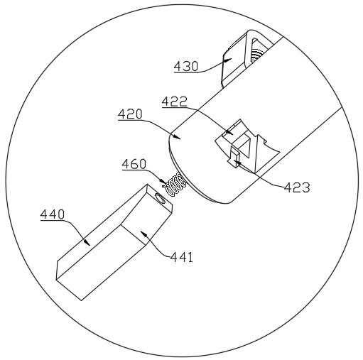
[0071] When hoisting scarifier 1, if figure 1 As shown, the vertical conveying mechanism 300 is moved along the transverse conveying mechanism 200 to the top of the feed side material frame 500, and then the lifting plate 310 and the hook assembly 400 are driven downward by the endless chain 330, so that the boom 420 is aligned with the ear hole 11; Move the material frame 500 in the direction of the suspender 420 so that the suspender 420 is inserted into the ear hole 11. When inserted, the stopper 430 is pushed by the end face of the ear hole 11 and will shrink to the inside of the suspender 420, so that the suspender 420 passes through the ear hole 11; After the boom 420 passes through the ear hole 1, the stopper 430 protrudes from the outer circumference of the boom 420 to fix the ripper 1; Make the hook assembly 400 and the ripper 1 all be located in the shot blasting device 100, then, as Figure 4 The sealing plate 110 is closed as shown, and the shot blasting work is s...


PUM


Abstract

The invention discloses a conveying type shot blasting device for a scarifier. The conveying type shot blasting device comprises a shot blasting device, a transverse conveying mechanism, a longitudinal conveying mechanism, a lifting hook assembly and material frames, wherein the longitudinal conveying mechanism is slidably connected to the transverse conveying mechanism and comprises a lifting plate, the lifting plate is movably arranged in the vertical direction, the lifting hook assembly comprises a connecting plate, the connecting plate is rotationally arranged below the lifting plate, the connecting plate is slidably provided with a pair of parallel lifting rods used for lifting the scarifier, a telescopic stop block is arranged at the front end of the lifting rod, the pair of the material frames are arranged on the two opposite sides of the shot blasting device, one of the material frames is used for feeding, the other material frame is used for goods discharging, lug holes are located on the upper portion when scarifiers are placed on the material frames, the connecting lines of the axes of the lug holes are in a horizontal state, a pair of ejector rods is arranged at the goods discharging position, and the ejector rods are coaxial with the lug holes when the scarifiers conduct discharging, and the ejector rods are arranged in the normal direction of the axis in a moving mode. Uniform shot blasting processing can be performed on the peripheries of the scarifiers, the shot blasting quality is improved, the use safety is high, and the scarifiers are convenient to feed and take out, convenient to store and small in occupied area.

Description

technical field [0001] The invention belongs to the technical field of engineering machinery parts processing, and in particular relates to a conveying shot blasting device for a ripper. Background technique [0002] Scarifiers are widely used in engineering construction, and they have the functions of crushing and scarifying. Usually connected to excavators and bulldozers, it is generally a single-tooth structure with high structural strength, high hardness, and strong digging and cutting force. The ripper mainly includes a main body, with ear holes on the upper part for connection, and high-hardness tooth tips installed on the bottom. It is used for crushing rocks and frozen soil, and can also be used to excavate road surfaces. Since the working object is usually relatively hard, it is necessary to carry out surface hardening treatment on the main part when making a ripper. Commonly used hardening treatments include carburizing, nitriding, hard anodizing, quenching, shot...

Claims


Application Information

Patent Timeline
Patent Type & Authority Applications(China)
IPC IPC(8): B24C1/10B24C3/08B24C3/12B24C3/32B24C9/00
CPCB24C1/10B24C3/083B24C3/12B24C3/32B24C9/00
Inventor 吕波侯毅罗建军贺伟
Owner 成都中挖智能科技有限公司
Why Eureka
Try Eureka