Foldable multi-rotor unmanned aerial vehicle

A technology of multi-rotor drones and drones, which is applied in the field of drones, and can solve problems such as bump damage, increased drone footprint, and large wing footprints.

Active Publication Date: 2021-08-20
宁波阿瑞斯自动化技术有限公司
View PDF5 Cites 0 Cited by
  • Summary
  • Abstract
  • Description
  • Claims
  • Application Information

AI Technical Summary

Problems solved by technology

[0003] The front multi-rotor UAV often adopts the method of fixing the arm and the fuselage as one, which greatly increases the occupied area of ​​the UAV when it is in standby. Especially in the transportation process of the UAV, the wing occupies a large area and is easy to Caused bump damage, has always brought a certain economic loss
The use of folding arms solves this problem, while the existing arm folding structure is more complicated to unfold and fold, which cannot save time and effort

Method used


Image

  • Foldable multi-rotor unmanned aerial vehicle
  • Foldable multi-rotor unmanned aerial vehicle
  • Foldable multi-rotor unmanned aerial vehicle

Examples


Embodiment 1

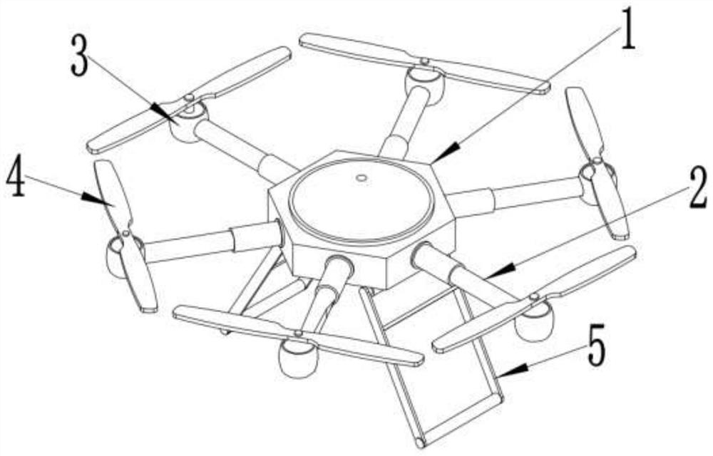
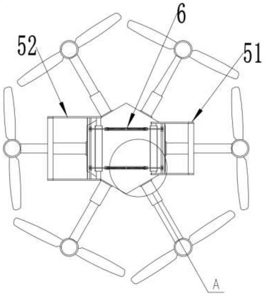
[0032] see Figure 1~4 , in an embodiment of the present invention, a foldable multi-rotor UAV includes a UAV main body 1; a plurality of crossbars 2 are evenly installed on the periphery of the UAV main body 1, and the outer ends of the crossbars 2 are fixed A drive seat 3 is installed, and the drive seat 3 is rotatably equipped with a wing 4, and the drive seat 3 drives the wing 4 to rotate, driving the drone main body 1 to rise and fly in the air; in the embodiment of the present invention, the horizontal The rod 2 is an electric telescopic rod structure, and the telescopic end of the cross rod 2 is fixedly connected with the drive seat 3. When the UAV is flying, the adjustment cross rod 2 is extended, and after the UAV lands, the adjustment cross rod 2 is shortened, thereby The UAV is put away to reduce the storage space of the UAV; the bottom of the UAV body 1 is rotatably equipped with a supporting mechanism 5, and the supporting mechanism 5 includes a left bracket 52 an...

Embodiment 2

[0040] see Figure 1~4 , in an embodiment of the present invention, a foldable multi-rotor UAV includes a UAV main body 1; a plurality of crossbars 2 are evenly installed on the periphery of the UAV main body 1, and the outer ends of the crossbars 2 are fixed A drive seat 3 is installed, and the drive seat 3 is rotatably equipped with a wing 4, and the drive seat 3 drives the wing 4 to rotate, driving the drone main body 1 to rise and fly in the air; in the embodiment of the present invention, the horizontal The rod 2 is an electric telescopic rod structure, and the telescopic end of the cross rod 2 is fixedly connected with the drive seat 3. When the UAV is flying, the adjustment cross rod 2 is extended, and after the UAV lands, the adjustment cross rod 2 is shortened, thereby The UAV is put away to reduce the storage space of the UAV; the bottom of the UAV body 1 is rotatably equipped with a supporting mechanism 5, and the supporting mechanism 5 includes a left bracket 52 an...


PUM


Abstract

The invention discloses a foldable multi-rotor unmanned aerial vehicle. The foldable multi-rotor unmanned aerial vehicle comprises an unmanned aerial vehicle main body; a plurality of cross rods are uniformly mounted on the peripheral side of the unmanned aerial vehicle main body, driving seats are fixedly mounted at the outer ends of the cross rods, and wings are rotationally mounted on the driving seats; the cross rod is of an electric telescopic rod structure, and the telescopic end of each cross rod is fixedly connected with the corresponding driving seat; a supporting mechanism is rotationally installed at the bottom of the unmanned aerial vehicle body and comprises a left support and a right support which are symmetrically arranged left and right, and an adjusting mechanism for driving the supporting mechanism to rotate is further installed at the bottom of the unmanned aerial vehicle body. When the unmanned aerial vehicle flies, the supporting mechanism is folded through the adjusting mechanism, the resistance of the unmanned aerial vehicle during flight is reduced, the energy consumption of the unmanned aerial vehicle is reduced, when the unmanned aerial vehicle lands, the supporting mechanism is unfolded through the adjusting mechanism, parking of the unmanned aerial vehicle is facilitated, and when the unmanned aerial vehicle is stored, the supporting mechanism is folded through the adjusting mechanism, and the storage space of the unmanned aerial vehicle is reduced.

Description

technical field [0001] The invention relates to the technical field of unmanned aerial vehicles, in particular to a foldable multi-rotor unmanned aerial vehicle. Background technique [0002] Unmanned aircraft, commonly known as: unmanned aircraft, unmanned aerial vehicle, unmanned aerial vehicle, unmanned combat aircraft, bee-type aircraft; in a broad sense, it refers to various remote-controlled aircraft that do not require a driver to board and drive, and generally refers to military aircraft. Fang's unmanned reconnaissance aircraft. [0003] The front multi-rotor UAV often adopts the method of fixing the arm and the fuselage as one, which greatly increases the occupied area of ​​the UAV when it is in standby. Especially in the transportation process of the UAV, the wing occupies a large area and is easy to The collision damage has always brought certain economic losses. This problem is solved by adopting the folding machine arm, but the unfolding and folding actions of...

Claims


Application Information

Patent Timeline
Patent Type & Authority Applications(China)
IPC IPC(8): B64C27/08B64C1/30
CPCB64C27/08B64C1/30
Inventor 张磊
Owner 宁波阿瑞斯自动化技术有限公司
Why Eureka
Try Eureka