
Filament separating device, spinning equipment and polyacrylonitrile carbon fiber precursor

A technology of yarn separation and equipment, which is applied in the field of spinning technology, can solve the problems of doubling, broken yarn, sticking, large difference in the width of the original yarn, and poor bundling, so as to reduce breakage, reduce mutual entanglement, and reduce broken yarn and hairy effect

Pending Publication Date: 2021-08-20
吉林碳谷碳纤维股份有限公司 +1
View PDF0 Cites 0 Cited by
  • Summary
  • Abstract
  • Description
  • Claims
  • Application Information

AI Technical Summary

Problems solved by technology

[0006] The present invention aims at the existing spinning equipment, when different types of polyacrylonitrile carbon fiber precursors pass through the surface of the spinning roller, the width of the precursors is quite different, the full package rate is low, the bunching is poor, and it is easy to cause doubling and breaking. In order to solve the technical problems of silk and sticking, a kind of splitting device, spinning equipment and polyacrylonitrile carbon fiber precursors are provided, so that the polyacrylonitrile carbon fiber precursors are constrained when running in the washing tank and oiling tank, which is conducive to maintaining the bundle of tows In the washing section, the tow can be prevented from diverging, and in the oiling section, the tow can be spaced apart, which is easy to operate, maximizes the spread of the silk web, improves the washing and oiling effect of the tow, and reduces the singleness of the tow wire break

Method used


Image

  • Filament separating device, spinning equipment and polyacrylonitrile carbon fiber precursor
  • Filament separating device, spinning equipment and polyacrylonitrile carbon fiber precursor
  • Filament separating device, spinning equipment and polyacrylonitrile carbon fiber precursor

Examples


Embodiment 1

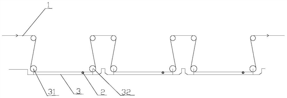
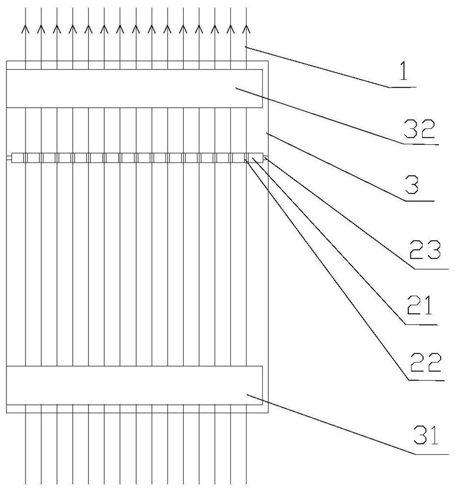
[0061] Such as Figure 1 to Figure 6 As shown, the present invention discloses a spinning device 2 and spinning equipment with the spinning device 2, which are used to produce and prepare polyacrylonitrile carbon fiber precursors. Specifically, the thread separating device 2 includes a thread separating rod 21 and a plurality of thread separating grooves 22 arranged axially at intervals on the peripheral sidewall of the thread separating rod 21 , and each thread separating groove 22 is arranged circumferentially. The wire separating groove 22 includes a notch 221 and a groove bottom 222 , and the width of the wire separating groove 22 decreases from the notch 221 to the groove bottom 222 .

[0062] In the present invention, the present invention makes the polyacrylonitrile carbon fiber precursor be constrained when the water washing tank 3 and the oiling tank run by setting the splitting groove 22, keeps the interval between the tows 1, reduces the mutual entanglement of the t...

Embodiment 2

[0066] In the present invention, the inner side wall 223 of the splitting groove 22 is arranged smoothly, and the tow 1 is in contact with the inner side wall 223 of the splitting groove 22, which is not easy to produce hairy filaments and broken filaments, and improves the performance of the tow 1.

[0067] As an implementation of this embodiment, the inner side wall 223 of the wire dividing groove 22 is smoothly connected with the groove bottom 222 of the wire dividing groove 22, so as to further improve the bundling performance of the wire dividing groove 22 on the tow 1, and Reduce broken filaments and fuzz in tow 1. At the same time, the relative concentration of stress at the junction of the inner wall 223 and the groove bottom 222 of the wire separating groove 22 is avoided, which will affect the strength of the tow 1 .

[0068] Further, the inner side wall 223 of the wire separating groove 22 is a smooth arc-shaped side wall;

[0069] Furthermore, the center of the ci...

Embodiment 3

[0071] In the present embodiment, the width of the dividing groove 22 is positively correlated with the number of monofilaments forming the tow 1 . Specifically, the greater the number of monofilaments forming the tow 1, the larger the width of the corresponding splitting groove 22, so that the tows 1 can all fall into the splitting groove 22, avoiding the occurrence of adhesion between adjacent tows 1 .

[0072] More specifically, the width of the notch 221 of the filament separating groove 22 is positively correlated with the number of monofilaments forming the tow 1 .

[0073] As an implementation of this embodiment, the number of monofilaments forming the tow is 1K-3K, and the width of the notch 221 of the wire dividing groove 22 is 6-12mm;

[0074] The number of monofilaments forming the tow is 6K-12K, and the width of the notch 221 of the wire dividing groove 22 is 10-18mm;

[0075] The number of monofilaments forming the tow is 24K-25K, and the width of the notch 221 ...


PUM

PropertyMeasurementUnit
elongation at breakaaaaaaaaaa

Abstract

The invention discloses a filament separating device, spinning equipment and a polyacrylonitrile carbon fiber precursor. The filament separating device comprises a filament separating rod and a plurality of filament separating grooves formed in the circumferential side wall of the filament separating rod at intervals in the axial direction; each filament separating groove is formed in the circumferential direction; each filament separating groove comprises a groove opening and a groove bottom; and the width of each filament separating groove is reduced from the corresponding groove opening to the corresponding groove bottom. According to the invention, by arranging the filament separating grooves, the polyacrylonitrile carbon fiber precursor is restrained when running in a washing groove and an oiling groove, the interval of tows is kept, the mutual winding of the tows is reduced, a large number of stiff filaments are prevented from being generated in a tow forming stage, broken filaments are prevented from being wrapped in the tows, and continuous spinning operation is ensured; by arranging the filament separating grooves, the filament width can be expanded to the maximum extent, the full bobbin rate of the precursor is increased, and the full bobbin rate of the precursor reaches 85% or above; and the width of each filament separating groove is reduced from the corresponding groove opening to the corresponding groove bottom, so that the bundling property of the tows is kept, the washing and oiling effects of the tows are improved, and the monofilament breakage of the tows is reduced.

Description

technical field [0001] The invention belongs to the technical field of spinning technology, and in particular relates to a spinning device, spinning equipment and polyacrylonitrile carbon fiber precursors. Background technique [0002] The preparation process of polyacrylonitrile carbon fiber precursor generally includes the following steps: preparation of spinning stock solution and spinning, coagulation bath forming, one or more washing and drawing, oiling, drying and winding and winding, usually in the spinning equipment completed. The tow formed in the coagulation bath is wound on multiple spinning rolls in turn, and enters the washing tank and oiling tank under the guidance of the spinning rolls to complete the steps of washing, drafting and oiling. [0003] During the continuous operation of the spinning equipment, the monofilaments in the tow can be relatively scattered and wound on the spinning rolls, so that the distribution of the monofilaments in the tow between ...

Claims


Application Information

Patent Timeline
Patent Type & Authority Applications(China)
IPC IPC(8): D02J1/18D01D13/00
CPCD01D13/00D02J1/18
Inventor 陈海军赵云峰张海鸥李凯宋德武姜彦波郭甲东吕红宇王学英魏璐瑶王辉陈浩王晓杰
Owner 吉林碳谷碳纤维股份有限公司
Learn More