A graded combustion chamber head with a swirling pre-diaphragm plate structure

A technology of pre-membrane plate and combustion chamber, which is applied in the direction of combustion chamber, continuous combustion chamber, combustion method, etc., to achieve the effects of improving combustion performance and emission performance, improving premixing effect, and improving spatial distribution of fuel oil

Active Publication Date: 2022-08-02
AERO ENGINE ACAD OF CHINA
View PDF11 Cites 0 Cited by
  • Summary
  • Abstract
  • Description
  • Claims
  • Application Information

AI Technical Summary

Problems solved by technology

Most of the disclosed pre-membrane plates are cylindrical or conical pre-membrane plates, such as the structure shown in Chinese Patent Application No. 201610860748.8; or blade pre-membrane plates, such as the structure shown in Chinese Patent Application No. 201810472110.6; both have a certain improvement in fuel mist However, there is still room for further research and improvement

Method used


Image

  • A graded combustion chamber head with a swirling pre-diaphragm plate structure
  • A graded combustion chamber head with a swirling pre-diaphragm plate structure
  • A graded combustion chamber head with a swirling pre-diaphragm plate structure

Examples


Embodiment Construction

[0041] The present disclosure will be further described in detail below in conjunction with the accompanying drawings and embodiments. It should be understood that the specific embodiments described herein are only used to explain the related content, but not to limit the present disclosure. In addition, it should be noted that, for the convenience of description, only the parts related to the present disclosure are shown in the drawings.

[0042] It should be noted that the embodiments of the present disclosure and the features of the embodiments may be combined with each other unless there is conflict. The present disclosure will be described in detail below with reference to the accompanying drawings and in conjunction with the embodiments.

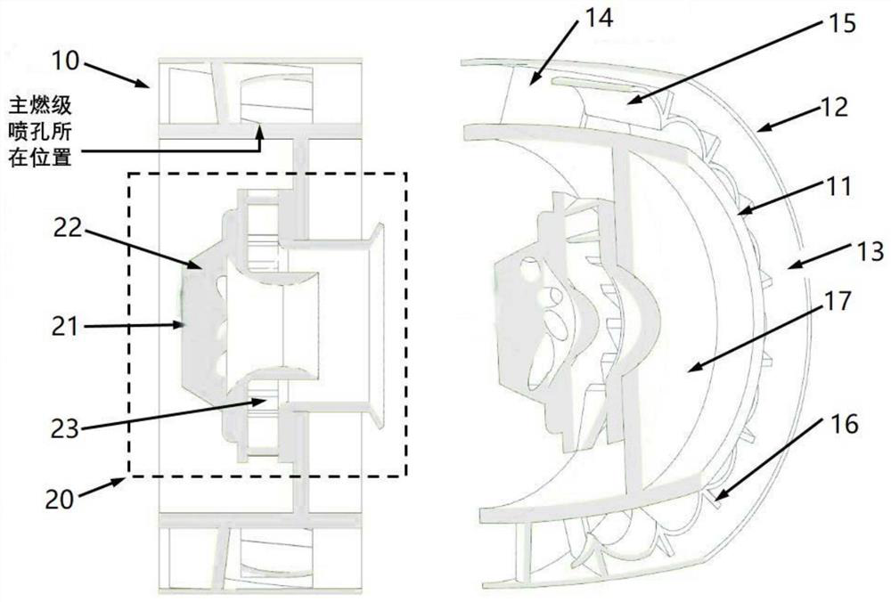
[0043] According to the first embodiment of the present disclosure, a staged combustion chamber head with a swirling pre-diaphragm plate structure is provided, which adopts a centrally staged structure, and includes a main combustion ...


PUM


Abstract

The present disclosure provides a staged combustion chamber head with a swirling pre-diaphragm plate structure, comprising: a pre-combustion stage, and a main combustion stage sheathed outside the pre-combustion stage; the main combustion stage includes an inner ring, and a sleeve sleeved outside the inner ring; the inner ring has a plurality of nozzle holes distributed in the circumferential direction; an annular air passage is formed between the inner ring and the sleeve; Axial swirl vanes and swirling pre-film plates are arranged in sequence from front to back; a plurality of axial swirling vanes are provided, and the plurality of axial swirling vanes are arranged in the circumferential direction; the swirling pre-film The plate is annular, and the swirling pre-film plate is formed by a plurality of segmented arcs arranged in the circumferential direction; the spray holes are arranged directly on the arc ridge of the swirling pre-film plate, and any two adjacent ones are arranged. There are two segmented arcs between the nozzle holes; the radial heights of the front and rear ends of the arc ridges are both greater than the radius of the outer surface of the inner ring and smaller than the radius of the inner surface of the sleeve.

Description

technical field [0001] The present disclosure relates to the technical field of aviation gas turbine combustors, and in particular, to a staged combustor head with a swirling pre-diaphragm plate structure. Background technique [0002] With the gradual progress of aero-engine technology, the combustion chamber of the engine adopts more staged combustion organization methods to achieve the purpose of high temperature rise or low emissions. In staged combustion, the pre-combustion stage mostly adopts the diffusion combustion method, and the main combustion stage mostly adopts the premixed combustion method. For this type of combustion chamber, a number of related patents have been applied at home and abroad, such as US patent application numbers 6363726 and 6389815 applied by GE in the United States, and patents 201210335832. [0003] The fuel volume of the main combustion stage is mainly ejected from the main combustion stage, and finally, under the action of the swirl airfl...

Claims


Application Information

Patent Timeline
Patent Type & Authority Patents(China)
IPC IPC(8): F23R3/34F23R3/38
CPCF23R3/346F23R3/38
Inventor 高浩卜陈曦焦哲许笑颜李金玮莫毅
Owner AERO ENGINE ACAD OF CHINA
Why Eureka
Try Eureka