Laser measurement system
A laser measurement system and laser emitting technology, which is applied in radio wave measurement systems, measurement devices, line-of-sight measurement, etc., can solve the problems of external power supply drive, increase in manufacturing cost and material cost, and achieve low power consumption and simple production and assembly , The effect of saving material cost
- Summary
- Abstract
- Description
- Claims
- Application Information
AI Technical Summary
Problems solved by technology
Method used
Image

Examples
Embodiment 1
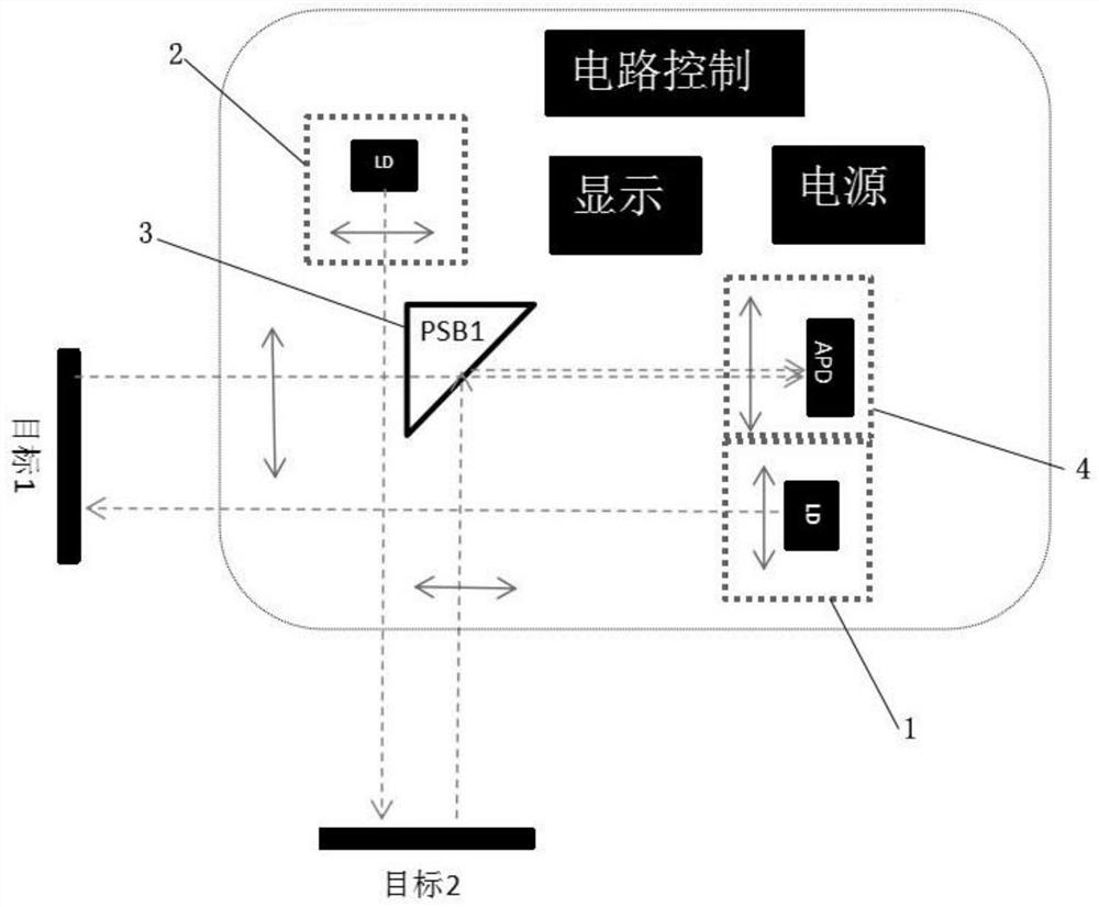
[0021] A laser measuring system such as figure 1 As shown, it includes: a first emitting module 1, which emits laser light; a second emitting module 2, which emits laser light, and has a different emission direction from the first emitting module; a light splitting module 3, which is arranged in the intersection area of the reflected light paths of the two laser beams, and Summarize the light beams; the receiving module 4 is used to receive the light splitting module to summarize the light beams and convert them into electrical signals.
[0022] In this embodiment, only one optical splitting module and receiving module are used to realize the distance measurement of dual lasers, and only one set of control circuit is needed, which saves material cost, reduces power consumption, and makes production and assembly easier.
[0023] In this embodiment, the emitting direction of the first emitting module is perpendicular to the emitting direction of the second emitting module.
...
Embodiment 2
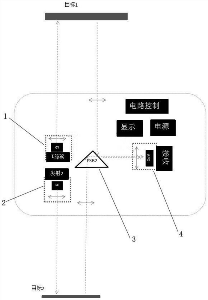
[0026] Such as figure 2 As shown, the difference between this embodiment and the previous embodiment is that the emitting direction of the first emitting module is opposite to that of the second emitting module.
[0027] Wherein the beam splitting module includes a beam splitter, the beam splitter includes a transmission surface, a first semi-reflective surface and a second semi-reflective surface, the reflected light of one of the first emission module and the second emission module passes through the transmission surface and then passes through the first Reflected by the transflective surface, and then transmitted by the second semi-transparent surface, it enters the receiving module, and another beam of reflected light enters the receiving module after being reflected by the second semi-transparent surface. The beam splitter is generally a triangular prism.
Embodiment 3
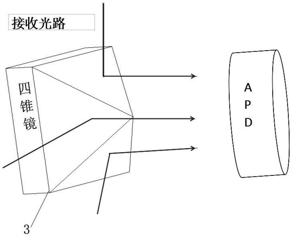
[0029] Such as image 3 As shown, the difference between this embodiment and the previous embodiment is that it also includes a third emitting module, and the emission direction between the emitting modules is cross-shaped, and the light splitting module includes a four-cone mirror, and the surface of the four-cone mirror is coated with a reflective film, the laser light emitted by the transmitting module is reflected back to the receiving module through different reflective films of the four-cone mirror.
[0030] The substantive effects of the above embodiment include: using one optical splitting module and receiving module to realize multi-laser ranging, only one set of control circuit is needed, material cost is saved, power consumption is reduced, and production and assembly are simpler.
[0031] Through the description of the above embodiments, those skilled in the art can understand that for the convenience and brevity of the description, only the division of the above-m...
PUM
 Abstract
Description
Claims
Application Information
 - R&D Engineer
- R&D Manager
- IP Professional
- Industry Leading Data Capabilities
- Powerful AI technology
- Patent DNA Extraction
Browse by: Latest US Patents, China's latest patents, Technical Efficacy Thesaurus, Application Domain, Technology Topic.
© 2024 PatSnap. All rights reserved.Legal|Privacy policy|Modern Slavery Act Transparency Statement|Sitemap