Imaging lens, projection light path system and projection equipment

An imaging lens and projection light technology, applied in optics, optical components, instruments, etc., can solve the problems of complex imaging lens structure, increase the size of the projector, increase the cost of the projector, etc., to improve the projection effect and reduce the weight and cost, the effect of reducing production cost

Pending Publication Date: 2021-08-20
成都传视科技有限公司
View PDF0 Cites 0 Cited by
  • Summary
  • Abstract
  • Description
  • Claims
  • Application Information

AI Technical Summary

Problems solved by technology

However, there are some problems in the above two short-focus projectors in the actual application process: one is that a large number of lenses will be set in the imaging lens to ensure the projection quality, which makes the structure of the imaging lens complex and the manufacturing cost is high; the other is that The use of an aspheric mirror will increase the size of the projector, and the cost of the aspheric mirror itself is relatively high, and the use of an aspheric mirror will cause a large imaging error, which not only increases the cost of the projector but also reduces shadow effect

Method used


Image

  • Imaging lens, projection light path system and projection equipment
  • Imaging lens, projection light path system and projection equipment

Examples


Embodiment 1

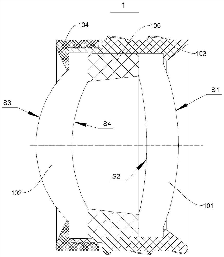
[0030] Please refer to figure 1 , the present embodiment provides an imaging lens 1, including a first lens 101 and a second lens 102 oppositely arranged; wherein, the first lens 101 includes a first convex surface S1 and a first concave surface S2, and the second lens 102 includes a second convex surface S3 and the second concave surface S4, the first convex surface S1 of the first lens 101 and the second concave surface S4 of the second lens 102 are incident surfaces, the first concave surface S2 of the first lens 101 and the second convex surface S3 of the second lens 102 Both are outgoing surfaces. The second concave surface S4 of the second lens 102 is used to receive the light emitted by the second concave surface S2 of the first lens 101 , and finally the light is projected onto the screen through the second convex surface S3 of the second lens 102 .

[0031] In this embodiment, by setting the first concave surface S2 of the first lens 101 toward the second concave surf...

Embodiment 2

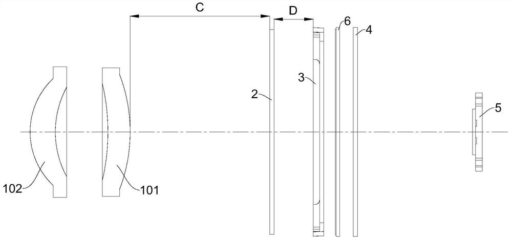
[0036] Please refer to figure 2 , this embodiment provides a projection optical path system, including a light source 5, a first lens 4, an LCD screen 3, a second lens 2, and the above-mentioned imaging lens 1 arranged in sequence along the optical path, wherein the first lens 101 of the first lens A convex surface S1 is used to receive the light emitted by the second lens 2 .

[0037]It should be noted that the first lens 4 in this embodiment adopts a homogeneous Fresnel lens, and the second lens 2 adopts a trapezoidal Fresnel lens. The above-mentioned Fresnel lens belongs to the common configuration in LCD projection systems, wherein The homogeneous Fresnel lens can convert the point light source into parallel light, while the trapezoidal Fresnel lens converges the parallel light onto the imaging lens 1, and then the imaging lens 1 enlarges the image and projects it on the projection screen for imaging.

[0038] By applying the above-mentioned imaging lens 1 to the project...


PUM


Abstract

The invention belongs to the technical field of projection equipment, and provides an imaging lens, a projection light path system and projection equipment. The imaging lens comprises a first lens and a second lens which are oppositely arranged, the first lens comprises a first convex surface S1 and a first concave surface S2, and the second lens comprises a second convex surface S3 and a second concave surface S4; the first convex surface S1 of the first lens and the second concave surface S4 of the second lens are incident surfaces, and the first concave surface S2 of the first lens and the second convex surface S3 of the second lens are emergent surfaces. On the basis of meeting normal projection of short-focus projection equipment, only the two lenses are adopted as the projection lenses of the imaging lens, so that the structure of the imaging lens can be simplified, and the manufacturing cost of the imaging lens is reduced; meanwhile, with the imaging lens adopted, the rear working distance of the imaging lens in a projection light path system can be shortened, so that a smaller projection ratio is obtained, a picture with a larger size is projected within a shorter projection distance, and the projection effect is improved.

Description

technical field [0001] The present invention relates to the technical field of projection equipment, in particular to an imaging lens, a projection optical path system and projection equipment. Background technique [0002] A short-throw projector is a projection device with a very short throw ratio. With the help of a short-throw projector, it is possible to watch bright and colorful large-screen images in any room, classroom, and conference room. [0003] There are two types of short-focus projectors currently on the market. One is a reflective projector. The working principle is to add an aspheric mirror in front of the short-focus projection lens, and project it onto the screen after reflection. The other is an ordinary short-focus projector. However, there are some problems in the above two short-focus projectors in the actual application process: one is that a large number of lenses will be set in the imaging lens to ensure the projection quality, which makes the stru...

Claims


Application Information

Patent Timeline
Patent Type & Authority Applications(China)
IPC IPC(8): G02B13/18G02B13/16G02B13/24G03B21/14
CPCG02B13/003G02B13/16G02B13/24G03B21/14
Inventor 武宇
Owner 成都传视科技有限公司
Why Eureka
Try Eureka