
Optical signal transceiving switching unit, distributed optical switching system and extension method thereof

A technology of switching unit and optical transmitting unit, which is applied in the field of optical network communication, can solve the problems of inconvenient expansion, difficulty in making optical crossbar switches, and high cost, and achieve the effect of mutual protection and on-demand expansion

Pending Publication Date: 2021-08-20
杭州兰特普光电子技术有限公司
View PDF0 Cites 1 Cited by
  • Summary
  • Abstract
  • Description
  • Claims
  • Application Information

AI Technical Summary

Problems solved by technology

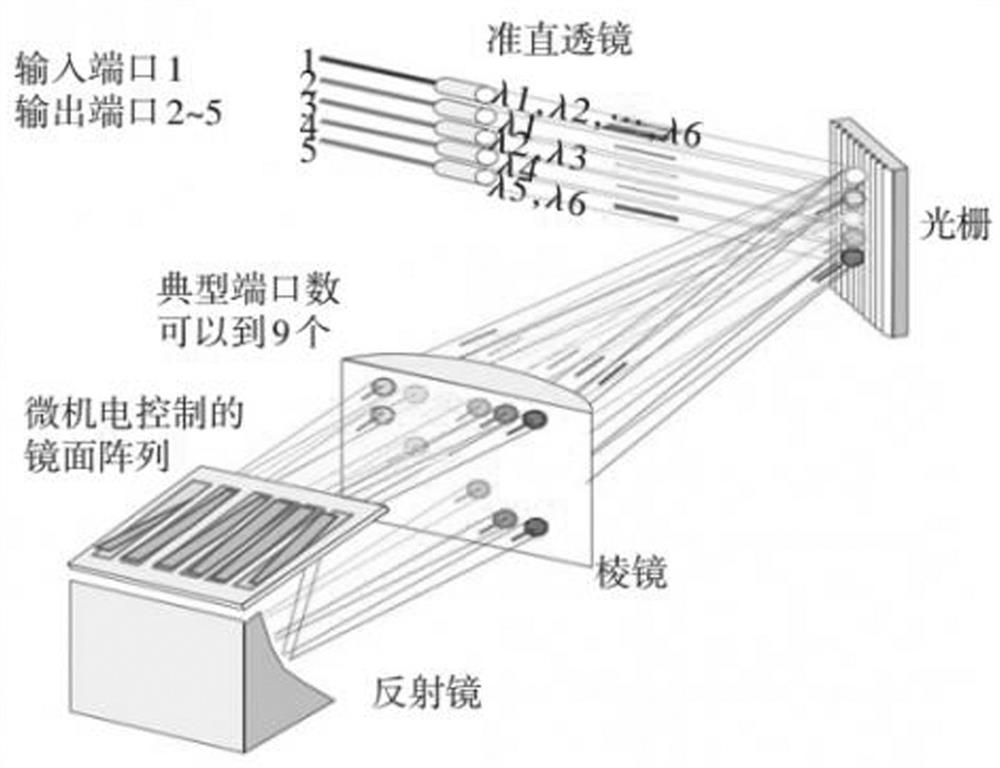
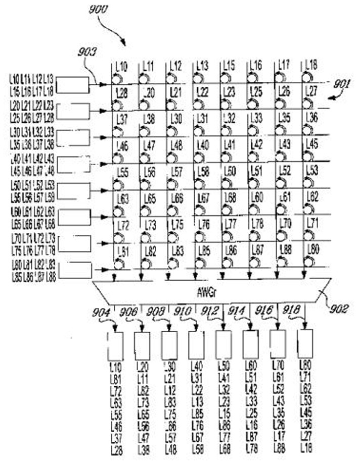
[0007] 3. The optical switching system based on the optical crossbar switch, the optical crossbar switch of this system is difficult to manufacture and the cost is high (see image 3 )
However, the above structures are all lumped optical switches, and the expansion of the total capacity is limited by the number of ports of the AWG and the optical crossbar switch, which is not convenient for arbitrary expansion.

Method used


Image

  • Optical signal transceiving switching unit, distributed optical switching system and extension method thereof
  • Optical signal transceiving switching unit, distributed optical switching system and extension method thereof
  • Optical signal transceiving switching unit, distributed optical switching system and extension method thereof

Examples


Embodiment 1

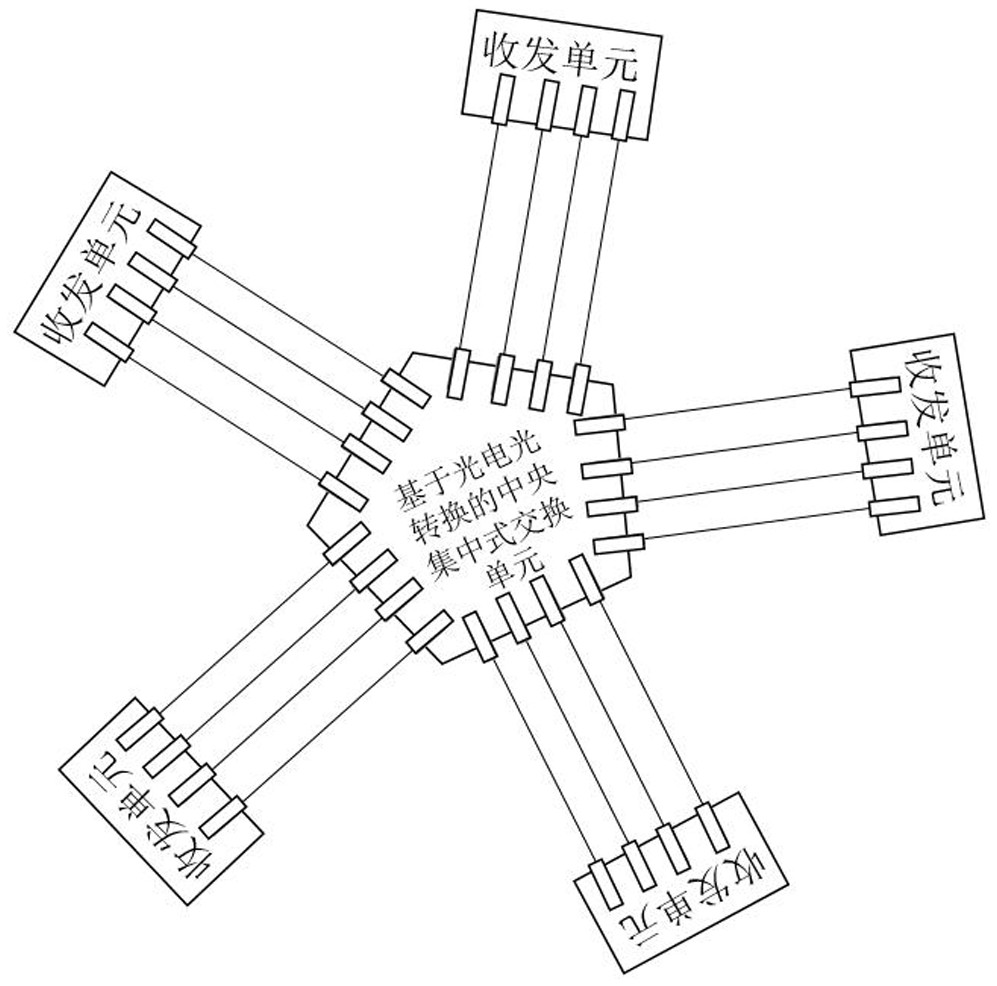
[0052] Embodiment 1: This embodiment is a distributed optical switching system, which has several nodes, and each node includes an optical signal sending and receiving switching unit.

[0053] Figure 7 It is a schematic diagram of the structure of the distributed optical switching system in the embodiment. The optical transceiver switching unit 1 in each node is directly interconnected with the optical transceiver switching units in the other 4 nodes through an optical fiber or a waveguide 2 to form a distributed optical switching system. fully connected structure.

[0054] In this example, each node in the distributed optical switching system has an optical signal transceiver switching unit, and each optical signal transceiver switching unit has N (in this example, N is greater than or equal to 4) input / output optical ports. Any 4 input / output optical ports of the unit are respectively connected to a certain input / output optical port on the optical signal transceiving and s...

Embodiment 2

[0071] Embodiment 2: as Figure 10 As shown, the non-fully connected distributed optical switching system in this embodiment is basically the same as that in Embodiment 1, the only difference is that the nodes in this example are not directly connected to each other, and there are Nodes can only be indirectly interconnected through one or several other nodes in the system.

[0072] In this example, the data transmission method between nodes in the distributed optical switching system is as follows:

[0073] A. When the sending end node and the receiving end node are directly interconnected, the data transmission method between the nodes is the same as the data transmission method in embodiment 1;

[0074] B. When the sending node and the receiving node are only indirectly interconnected through one or several other nodes in the system, the data transmission method is as follows:

[0075] The optical signal transceiving and switching unit of the sending end node obtains one o...

Embodiment 3

[0085] Embodiment 3: as Figure 11 As shown, the distributed optical switching system distributed in tree form in this embodiment is basically the same as that in Embodiment 2, the only difference is that the nodes in this embodiment are distributed in tree form, and the server clusters in the nodes The data of the (host computer) is transmitted and received through the optical signal receiving and exchanging unit interconnected with it.


PUM


Abstract

The invention relates to an optical signal transceiving switching unit, a distributed optical switching system and an expansion method thereof. The optical signal transceiving switching unit is provided with N input / output optical ports, each optical port can simultaneously transmit and receive optical signals, the optical signal transceiving switching unit comprises N * N cyclic addressing array waveguide grating routers, the N optical ports on one side serve as internal input / output optical ports, and the N optical ports on the other side serve as input / output optical ports of the optical transceiving switching unit; the N tunable optical modules are interconnected with the N internal input / output optical ports of the cyclic addressing array waveguide grating router in a one-to-one correspondence manner; the tunable optical module is provided with a light emitting unit and a light receiving unit; the control mainboard is electrically connected with the N tunable optical modules and is used for controlling the corresponding tunable optical modules to emit specified wavelength optical signals of the corresponding wavelengths according to the received management information; and the management information received by the control mainboard is sent by the upper computer or is obtained by demodulating the optical signal received by the optical receiving unit.

Description

technical field [0001] The invention relates to an optical signal sending and receiving exchange unit, a distributed optical exchange system and an extension method thereof. It is applicable to the technical field of optical network communication. Background technique [0002] In the information age, with the rapid growth of applications such as cloud computing, data centers, Internet of Things, virtual reality, and high-definition short videos, the amount of global data is growing explosively. It is expected that the annual growth of global data will remain at about 50% in the future. 90% of the global data comes from data centers. How to deal with large-scale massive data requires continuous expansion of the infrastructure of the big data center, especially the optical switching system equipment. [0003] In order to cope with the rapid growth of data volume, optical switching equipment not only needs to support large-capacity optical switching, but also requires the scal...

Claims


Application Information

Patent Timeline
IPC IPC(8): H04B10/40H04Q11/00
CPCH04B10/40H04Q11/0005H04Q2011/0007H04Q2011/0037
Inventor 赵佳生何建军
Owner 杭州兰特普光电子技术有限公司
Learn More