Density gradient microstructure, preparation method of density gradient microstructure and magnetically controlled switch

A microstructure and gradient technology, applied in the field of microfluidics, can solve the problems of weak real-time control capability and complex device structure, and achieve the effects of real-time control, increased liquid spreading speed, and obvious reverse cut-off effect.

Active Publication Date: 2021-08-24
BEIHANG UNIV
View PDF23 Cites 2 Cited by
  • Summary
  • Abstract
  • Description
  • Claims
  • Application Information

AI Technical Summary

Problems solved by technology

[0003] The existing technology has the disadvantages of complex device structure and weak real-time control ability for the realization of liquid directional delivery.

Method used


Image

  • Density gradient microstructure, preparation method of density gradient microstructure and magnetically controlled switch
  • Density gradient microstructure, preparation method of density gradient microstructure and magnetically controlled switch
  • Density gradient microstructure, preparation method of density gradient microstructure and magnetically controlled switch

Examples


Embodiment 1

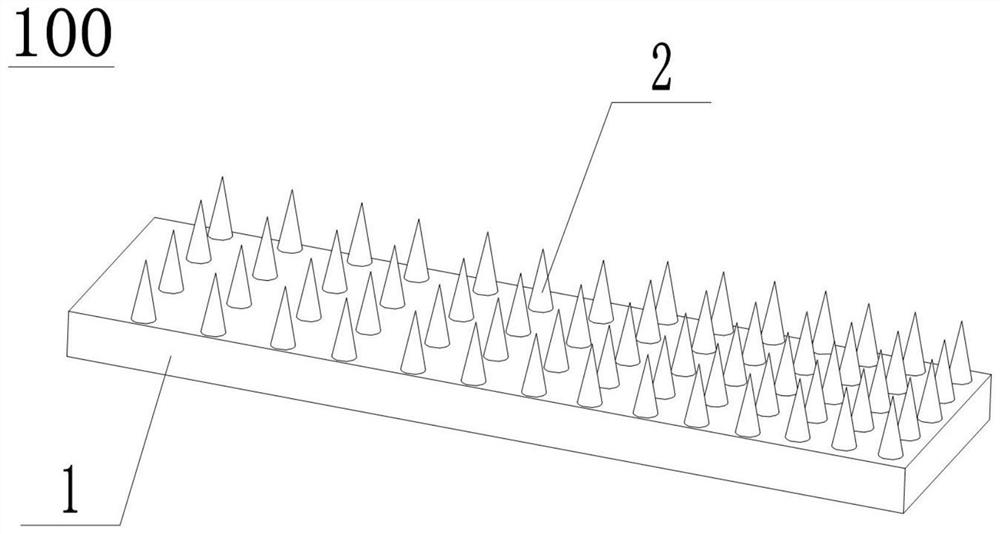
[0044] Such as figure 1 As shown: the present embodiment provides a density-gradient microstructure 100, including a substrate 1, a plurality of array regions are arranged on the substrate 1, and each array region includes a number of evenly distributed micropillars 2, and micropillars 2 in different array regions The spacing of the micropillars increases from one end of the substrate 1 to the other end of the substrate 1, and the micropillars 2 are all magnetic.

[0045] In this embodiment, the shape of the micropillar 2 is cone, cylinder or prism.

[0046] In this embodiment, the width of the substrate 1 is 5-10 mm, the length of the substrate 1 is 30-50 mm, the distance between the micro-columns 2 in the same array area is the same, and the distance d of the micro-columns 2 is 150-550 μm. The gradient difference between the pitches of the micropillars 2 in adjacent array regions is the same, and the gradient difference Δ is 10 μm. For example, the pitch of micropillars 2 ...

Embodiment 2

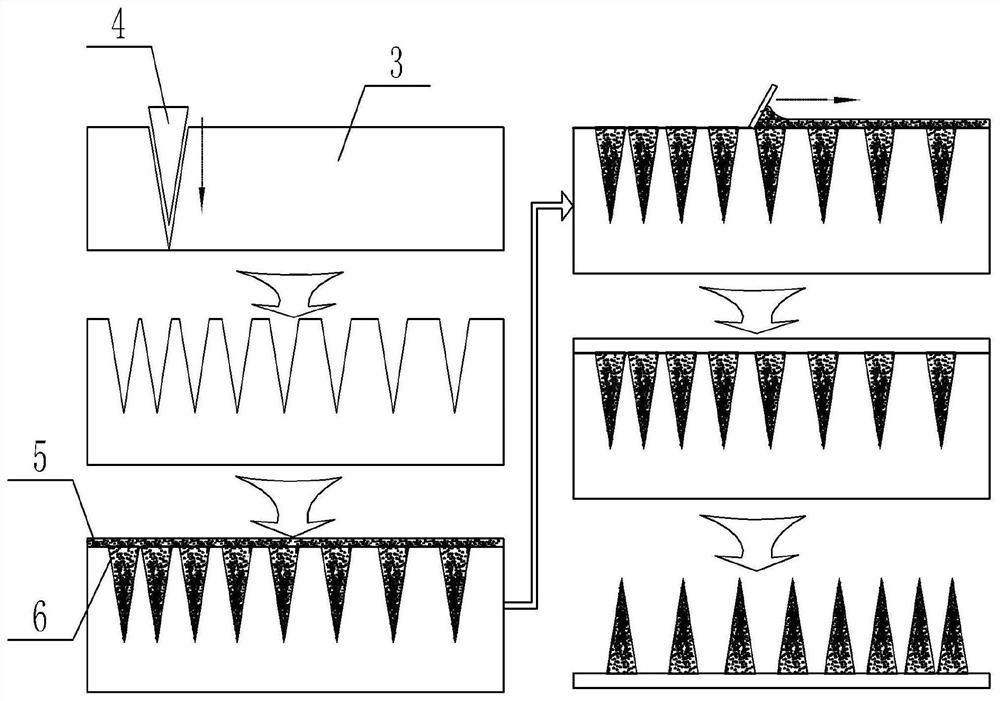
[0051] Such as Figure 2-Figure 4 Shown: This embodiment provides a method for preparing the density gradient microstructure 100 of Embodiment 1, including the following steps:

[0052] S1: The mold 4 with the same shape as the microcolumn 2 is used to make holes point by point on the substrate 3. The spacing of the holes is the same as that of the microcolumns 2 of the density gradient microstructure 100. Specifically, this embodiment adopts a tapered The mold 4 has a cone tip angle of 15°, the mold 4 is a steel needle, the substrate 3 is a paraffin plate, and the depth of the cone hole is between 100 and 500 μm;

[0053] S2: vacuumize the prepared hole, and pour the mixed solution 6 with magnetic particles 5 into the prepared hole;

[0054] S3: Vacuum again, scrape off the excess mixed solution 6 with magnetic particles 5, continue pouring the mixed solution 6 onto the substrate 3 to form the matrix 1, and ensure that the average thickness of the recasting is between 2 and ...

Embodiment 3

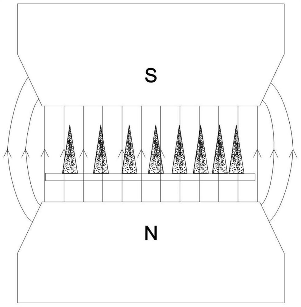
[0062] Such as Figure 5-Figure 10c As shown: this embodiment provides a magnetic control switch 200, including the density gradient microstructure 100 of the first embodiment, the density gradient microstructure 100 is located in the micro-channel 7, the micro-channel 7 is located in the magnetic field, and the micro-flow One end of the channel 7 is an N pole, and the other end of the microchannel 7 is an S pole. The microchannel 7 is made of PDMS. The width of the microchannel 7 is 5 mm and the length is 50 mm. The distance between the tops of 7 is 2 mm, the middle part of the micro-channel 7 is provided with an inlet 8, and the inlet 8 is connected to the capillary glass tube 11, one end of the micro-channel 7 is the first outlet 9, and the other end of the micro-channel 7 is the second outlet 10. One end (sparse end) of the matrix 1 of the density gradient microstructure 100 corresponds to the first outlet 9, the other end (dense end) of the matrix 1 corresponds to the sec...


PUM


Abstract

The invention discloses a density gradient microstructure, a preparation method of the density gradient microstructure and a magnetically controlled switch, and relates to the technical field of microfluidics, the density gradient microstructure comprises a substrate, the substrate is provided with a plurality of array areas, each array area comprises a plurality of uniformly distributed micro columns, the distance between the micro-columns in different array areas is sequentially increased from one end of the base body to the other end of the base body, and the micro-columns are magnetic. The micro-columns of the density gradient microstructure form a density array area according to a certain rule, and the micro-columns can directionally deflect under the condition of an external magnetic field. The deflection angle of the microcolumn can be controlled by controlling the intensity of the magnetic field, and then the spreading direction of the liquid film is controlled, so that directional regulation and control of the liquid can be realized. The liquid spreading direction can be regulated and controlled in real time in the field of microfluidics, and a new thought is provided for microfluidics, directional screening of drugs and design of microfluidic chips.

Description

technical field [0001] The invention relates to the field of microfluidic technology, in particular to a density gradient microstructure, a preparation method of the density gradient microstructure and a magnetic control switch. Background technique [0002] The research on the directional control of liquid spreading is of great significance in the fields of microfluidics such as physical chemistry and biomedicine. In recent years, the liquid directional control means mainly include surface microstructure and external field control, wherein the surface microstructure realizes liquid directional control means including gradient microfluidic channels (the Chinese patent with the publication number CN111359683A discloses a non-powered droplet delivery method). Gradient microfluidic channel and preparation method thereof), pumpless super-lyophobic coating (a Chinese patent with publication number CN110898865A discloses a new general-purpose pumpless directional transport liquid ...

Claims


Application Information

Patent Timeline
Patent Type & Authority Applications(China)
IPC IPC(8): B01L3/00
CPCB01L3/502715B01L3/50273B01L3/502707B01L3/502738B01L2200/022B01L2200/025B01L2400/043
Inventor 陈华伟刘光张力文陈登科
Owner BEIHANG UNIV
Why Eureka
Try Eureka