Deslagging device of fan coal mill

A technology of fan coal mill and weighing device, which is applied in the field of machinery, can solve the problems of increasing the wear of components such as the impact wheel, and the slag of the fan coal mill cannot be discharged in time, so as to achieve the effect of easy transfer

Pending Publication Date: 2021-08-24
CHANGCHUN POWER GENERATION EQUIP PLANT +2
View PDF0 Cites 0 Cited by
  • Summary
  • Abstract
  • Description
  • Claims
  • Application Information

AI Technical Summary

Problems solved by technology

[0005] The purpose of the present invention is to provide a fan coal mill slag discharge device, which can solve the problem that the existing fan coal mill can not discharge the slag that cannot be ground

Method used


Image

  • Deslagging device of fan coal mill
  • Deslagging device of fan coal mill

Examples


Embodiment 1

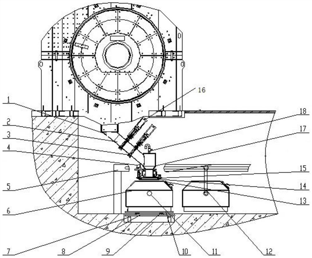
[0019] see figure 1 , the present invention provides a technical solution: see figure 1 , the slag discharge device of the fan coal mill of the present invention includes a pipe with different diameters and a slag discharge pipe 2 connected to the bottom of the iron accumulation tank of the casing 1, and the slag discharge pipe 2 is provided with two pneumatic shut-off valves, from top to bottom, Respectively referred to as the primary shut-off valve 16 and the secondary shut-off gate valve 3, the tail end of the slag discharge pipeline 2 is connected to the sealed cabin 17, and the top end of the sealed cabin 17 is provided with a pressure relief valve 18, and the lower end is connected to the protective cover 15 and the sealing ring 14, and the sealing The outside of the cabin 17 is provided with a compression cylinder 4 for squeezing the sealing ring 14 for sealing. Below the sealing ring 14 is a transfer box 6 with an observation window 13. The transfer box 6 is installed ...

Embodiment 2

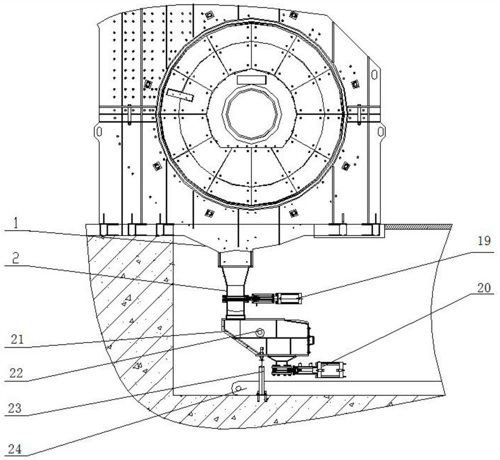
[0022] refer to figure 2 , the slagging device of the fan coal mill of the present invention comprises a different-diameter pipeline 1 and a slag discharge pipeline 2 connected to the lower iron tank of the casing 1, the slag discharge pipeline 2 is provided with a first pneumatic shut-off valve 19, and the slag discharge The lower end of the pipeline 2 is connected to the pebble coal storage box 21, and the pebble coal storage box 21 is provided with a material level gauge 22, and the box body is fixed on the ground through a support seat 23, and a second pneumatic shut-off valve 20 is provided under the box body, and the transfer device is Pebble coal conveyor belt24.

[0023] The working process of the present invention is: when the coal mill is running, the first pneumatic shut-off valve 19 on the slag discharge pipeline 2 is opened, the second pneumatic shut-off valve 20 is closed, and the slag material discharged from the coal mill is stored in the gravel In the coal s...


PUM


Abstract

The invention discloses a deslagging device of a fan coal mill, and belongs to the technical field of machinery. The deslagging device comprises a deslagging pipeline, a deslagging pneumatic door, a material box, a weighing device and a transfer device; the deslagging pipeline is arranged below an iron accumulation groove of a shell, the deslagging pneumatic door is connected to the deslagging pipeline, the material box is connected to the lower part of the deslagging pipeline, and the weighing device is arranged on the material box; when the weighing device gives out a full box alarm, the deslagging pneumatic door is controlled to act, the material box is conveyed to a dumping place through the transfer device, and dumping of materials is completed. Compared with an original deslagging mode that slag is stacked in an iron accumulation groove, the deslagging device device of the fan coal mill achieves the function of discharging slag such as iron blocks and coal gangue which cannot be ground in the coal mill out of the machine shell in time, and secondary abrasion of the slag, which cannot be ground, to a beating wheel and a lining plate is avoided; and in addition, the deslagging device of the fan coal mill can easily transfer materials through the transfer device, and the problem that an iron accumulation groove of an original fan coal mill is difficult to clean is solved.

Description

technical field [0001] The invention relates to the technical field of machinery, in particular to a slag discharge device for a fan coal mill. Background technique [0002] The material composition of coal is very complex, which is often mixed with non-grindable ore or scrap iron, as well as hard-to-grind coal gangue and other substances. Their existence will undoubtedly increase the wear on the internal components of the fan coal mill. [0003] The existing fan coal mill is not equipped with a slag discharge device, and the ungrindable slag is accumulated in the iron accumulation tank at the bottom of the casing under the action of gravity, and can only be cleaned when the coal mill is shut down for maintenance. And owing to be provided with striking wheel in the casing, the space is narrow and narrow, and this has increased the difficulty and the workload of clearing the accumulation iron groove greatly. At the same time, because the ungrindable slag cannot be discharged...

Claims


Application Information

Patent Timeline
IPC IPC(8): B02C23/00B65G65/40B65G65/42
CPCB02C23/00B65G65/40B65G65/42
Inventor 孟凡荣梁爽张喜春杨柳高航李文东张丽娜任权谢维萍杜蒙闫旭刘海鹰郑玉清
Owner CHANGCHUN POWER GENERATION EQUIP PLANT
Why Eureka
Try Eureka