

Bristle planting equipment for special-shaped brush
A hair-planting and brush technology, which is applied in the field of hair-planting equipment for special-shaped brushes, can solve problems affecting work efficiency and hair-planting effect, the overall shape and arrangement are easy to collapse, and harmful heavy metal ions to the human body, etc., so as to facilitate the shaping of the brush head and ensure Compactness, the effect of increasing fluency
- Summary
- Abstract
- Description
- Claims
- Application Information
AI Technical Summary
Problems solved by technology
Method used
Image

Examples
Embodiment 2
[0063] Such as Figure 14 As shown, in this embodiment, as an explanation for the assembly of bristles, the assembly device 7 includes a bearing platform 7.1 arranged on the workbench, a bearing plate 3 arranged on the bearing platform 7.1 and a device The second flushing mechanism 2.5 above the transfer channel 2.2, the carrier plate 3 is arranged below the transfer channel 2.2, and the carrier plate 3 travels between the workbench 1 and the carrier platform 7.1, wherein the carrier platform 7.1 The bottom is provided with an assembled jacking cylinder 7.3, and a linear moving track 7.2 is arranged on the carrying platform 7.1, and a scalding device 12 is arranged above the moving track 7.2, and the carrying plate 3 completes the hair planting Finally, the workbench 1 drives the carrying plate 3 to below the scalding device 12, and the carrying plate 3 can travel on the moving track 7.2. 1 to switch positions.
[0064] Such as Figure 15 As shown, a plurality of limit seat...
Embodiment 3
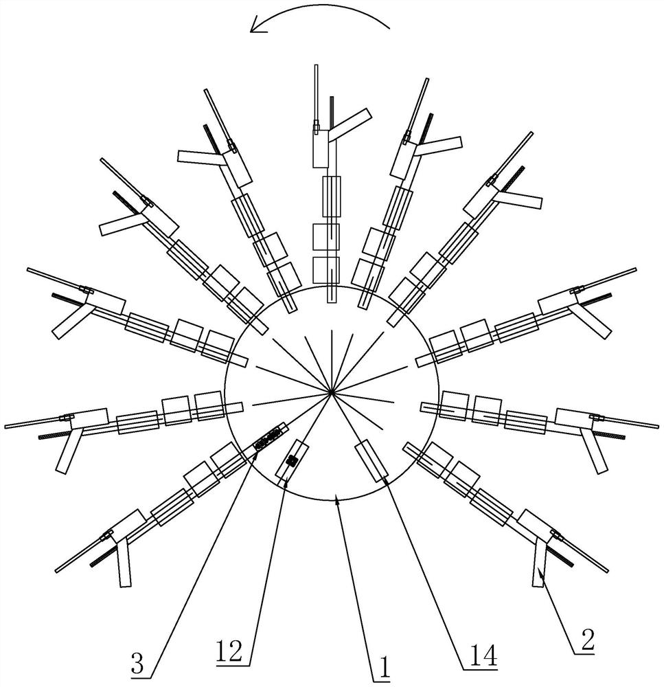
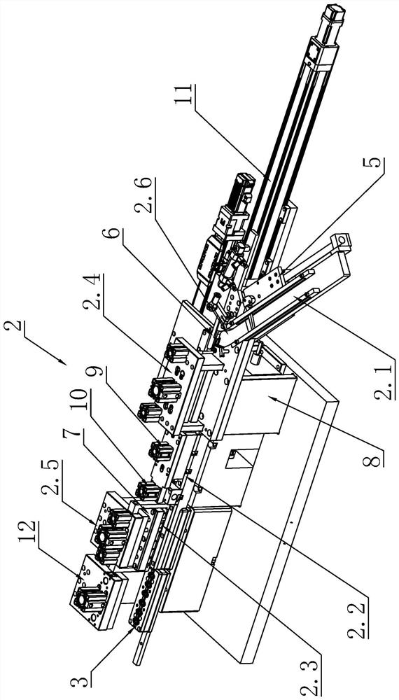
[0072] Such as figure 2 and Figure 5 to Figure 7 As shown, on the basis of the above, the hair-planting module 2 is set at intervals in the circumferential direction on the workbench 1, and the hair removal channel 2.1 is arranged obliquely with respect to the transfer channel 2.2, thereby improving the space utilization rate outside the workbench, and the hair removal The passage 2.1 is provided with a relatively curved preparation passage 2.6, and the bristle outlet 2.11 is arranged at the end of the preparation passage 2.6, so that the bristle outlet 2.11 is relatively perpendicular to the hair removal plate 4, thereby ensuring that the bristles enter the removal The stability and fluency of the pores 4.1 increases the density of the bristles in the pores 4.1.
[0073] In order to increase the stability of the bristle output to the pores 4.1 when the bristles are output at the hair outlet 2.11, a pressure sensor 2.7 is provided at the corner of the preparation channel 2....
Embodiment 4
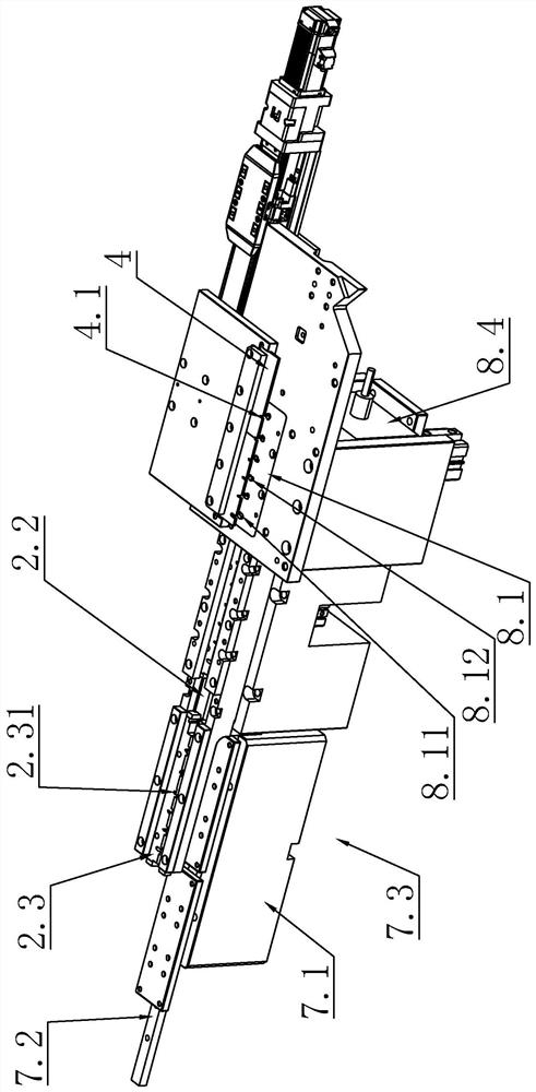
[0076] Such as Figure 9 As shown, on the basis of the above, the shaping station also includes a homogenizing device 8 located below the first flushing mechanism 2.4, and the homogenizing device 8 includes:
[0077] The hair-entry guide plate 8.1, the hair-entry guide plate 8.1 is fixed at the hair-entry position and is located between the hair-feeding plate 4 and the transfer channel 2.2, that is, the hair-entry guide plate 8.1 is located above the carrier 2.3, The hair-introduction guide plate 8.1 is provided with a bell mouth 8.11 corresponding to the loading pores 2.31, the bell mouth 8.11 has an expansion opening 8.12 larger than the loading pores 2.31, and the expansion opening 8.12 has a tendency to converge downwards , the lowermost end of the bell mouth 8.11 corresponds to the outline of the carrying pores 2.31, or is slightly larger than the outline of the carrying pores 2.31 to ensure the smoothness of the bristles entering the carrier 2.3, and the bell mouth 8.11 ...
PUM
 Abstract
Description
Claims
Application Information