
An automatic discharge machine for capacitor production

A technology of capacitors and discharge machines, which is applied in the direction of conveyor objects, transportation and packaging, packaging, etc., can solve the problems of affecting the discharge effect, low work efficiency, misplaced arrangement, etc., and achieve coherent and tight coordination of discharge operations, and improve Work efficiency, ensure the effect of orderly arrangement

Active Publication Date: 2021-10-01
南通海美电子有限公司
View PDF6 Cites 0 Cited by
  • Summary
  • Abstract
  • Description
  • Claims
  • Application Information

AI Technical Summary

Problems solved by technology

[0004] The above-mentioned scheme has the following deficiencies: 1. In this scheme, the material trough is driven up and down by the lifting cylinder to discharge material. The process of arranging the capacitors in the material trough and the process of putting the capacitors in the trough into the material tray need to be carried out step by step. The work efficiency is low; 2. This scheme pushes the capacitor into the trough through the vibrating plate. Since the capacitor is in the form of a cylinder, and there is a gap between the capacitor and the side wall of the trough, the friction is reduced and the capacitor is moved and arranged in the trough. , after the capacitors in the vertical state are filled in the trough, they are prone to dislocation arrangement, which leads to the uneven arrangement of the capacitors in the tray after discharge, which affects the subsequent processing; For transportation and transmission, during the transportation and transmission of the material tray, it is easy to cause the capacitor to dump and skew due to inertia or shaking, which affects the discharge effect

Method used


Image

  • An automatic discharge machine for capacitor production
  • An automatic discharge machine for capacitor production
  • An automatic discharge machine for capacitor production

Examples


Embodiment Construction

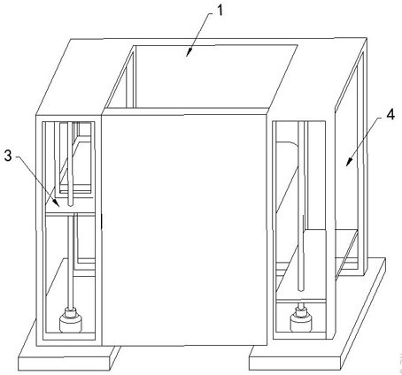
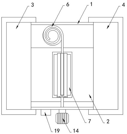
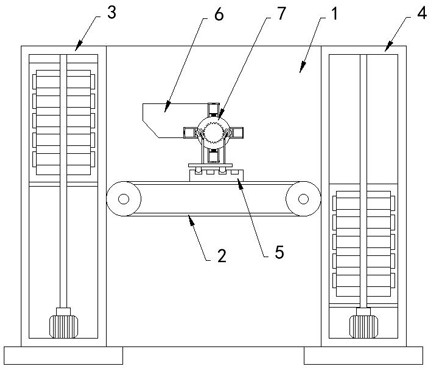
[0030] like Figure 1-7 As shown, a capacitor is produced with an automatic discharge machine, including a rack 1, a rack 1, a trace 2, a material disc supply mechanism 3, and a material discharge mechanism 4, and the transfer rail 2 can be a belt conveyor. The material disc supply mechanism 3 and the material disc dielectric 4 are all prior art, and there is no repertiction to the material disc supply mechanism 3, and the rack 1 is attached to the rack 6, the vibration disk 6 is attached. The output is provided with a discharge mechanism 7 for discharging the capacitor.

[0031] Specifically, the discharge mechanism 7 includes a rotating roller 8 and a plurality of side panels 9 fixed to the rotating roller 8, and several side plates 9 are arranged in parallel, and each set of side panels 9 and the circumference of the rotating roller 8 The tank 10 performed perpendicular to the transfer direction is formed, in the present embodiment, the side panel 9 has eight pieces, and the fou...


PUM


Abstract

The invention belongs to the technical field of capacitor production equipment, and in particular relates to an automatic discharge machine for capacitor production, including a frame, on which a transmission track, a tray supply mechanism and a tray unloading mechanism are arranged. A number of material trays are arranged in the tray supply mechanism, and a vibrating tray is installed on the frame, and the output end of the vibrating tray is provided with a discharge mechanism for discharging capacitors; the discharge mechanism includes rotating rollers and fixed A plurality of side plates connected to the rotating roller are arranged in parallel in pairs, and each group of side plates and the surrounding side walls of the rotating roller form a trough perpendicular to the conveying direction. The invention can make the process of arranging the capacitors in the trough and the process of putting the capacitors in the trough into the material pan be carried out synchronously, which improves the working efficiency. The problem of misalignment in the slot occurs, ensuring that the capacitors are discharged neatly, which is conducive to subsequent processing.

Description

Technical field [0001] The present invention belongs to the technical field of capacitor production equipment, in particular, involving an automatic discharge machine for capacitor production. Background technique [0002] With the growth rate of electronic information technology, the update of digital electronic products is increasing and faster, and the capacitor is important components in the tuning circuit of digital electronics, for storing power and electricity. [0003] According to the retrieval, the National Patent Publication No. CN 106206084 B discloses a capacitor automatic discharge machine, including a rack, a material supply mechanism, a capacitive drain mechanism, and a material discharge mechanism disposed on the rack, the The material discharged on the material disc supply mechanism is transferred to the capacitive drain mechanism by a transfer track, and the material tray after the material is rowed by the transfer rail to the material discharge mechanism; the ...

Claims


Application Information

Patent Timeline
Patent Type & Authority Patents(China)
IPC IPC(8): B65G47/14B65B35/34B65B43/42
CPCB65B35/34B65B43/42B65G47/1421
Inventor 邵淋锋
Owner 南通海美电子有限公司
Learn More