Supercharge Your Innovation With Domain-Expert AI Agents!

Novel optical film coating machine

An optical film and coating machine technology, applied in the field of coating machines, can solve the problems of affecting production efficiency, waste, large volume and weight of substrates, etc., and achieve the effect of improving production efficiency

Pending Publication Date: 2021-08-24
广西向东电子科技有限公司
View PDF0 Cites 0 Cited by
  • Summary
  • Abstract
  • Description
  • Claims
  • Application Information

AI Technical Summary

Problems solved by technology

However, the coating machine in the prior art applies glue unevenly, which affects the coating quality. Usually, the die wheel is used to roll the base material to adjust the amount of glue applied, but most of the die wheels for adjusting the amount of glue applied are fixed connections, which cannot The mold wheel with suitable material adjustment is not widely adaptable; and the existing coating machine has a relatively compact internal structure layout in order to save floor space, but the volume and weight of the rolled substrate are large, and it is installed in a limited space. The operation of material and unloading is relatively inconvenient, and operators spend a lot of time wasting on work such as changing models, loading, and unloading, which affects production efficiency

Method used


Image

  • Novel optical film coating machine
  • Novel optical film coating machine
  • Novel optical film coating machine

Examples


Embodiment Construction

[0028] The following will clearly and completely describe the technical solutions in the embodiments of the present invention with reference to the accompanying drawings in the embodiments of the present invention. Obviously, the described embodiments are only part of the embodiments of the present invention, not all of them. Based on the embodiments of the present invention, all other embodiments obtained by persons of ordinary skill in the art without making creative efforts belong to the protection scope of the present invention.

[0029] It should be noted that when a component is said to be "fixed" to another component, it can be directly on the other component or there can also be an intervening component. When a component is said to be "connected" to another component, it may be directly connected to the other component or there may be intervening components at the same time. When a component is said to be "set on" another component, it can be set directly on the other ...


PUM


Abstract

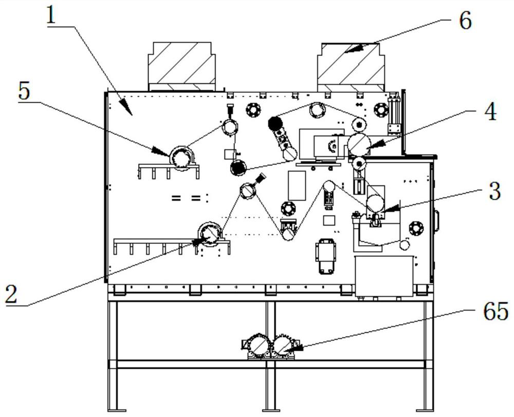
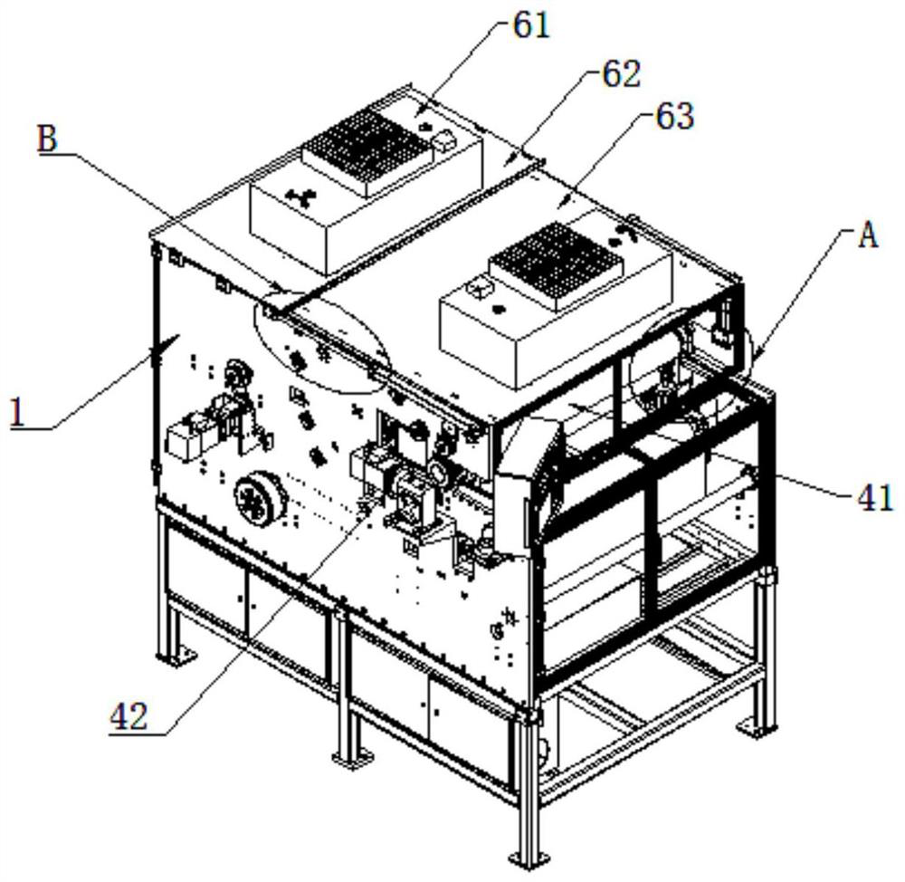
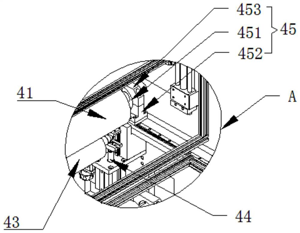
The invention discloses a novel optical film coating machine. The novel optical film coating machine comprises a base and further comprises an unwinding mechanism, a coating mechanism, a mold wheel mechanism, a winding mechanism, a heat dissipation mechanism and a heat dissipation translation driving mechanism which are mounted on the base, and the unwinding mechanism and the winding mechanism are detachably connected with the base. The heat dissipation mechanism is in translation sliding connection with the top of the base. The heat dissipation translation driving mechanism is mounted at the top of the base. The mold wheel mechanism comprises a mold wheel, a mold wheel driving assembly and a supporting wheel. The mold wheel is detachably connected with the base, and the mold wheel is rotationally connected with the base. The mold wheel driving mechanism is mounted on the base. The supporting wheel is located below the mold wheel and connected with the base in a lifting mode. The mold wheel, the unwinding mechanism and the winding mechanism are designed to be detachably connected, meanwhile, the top heat dissipation mechanism can conduct translational motion to adjust the position, the mold wheel, the unwinding mechanism and the winding mechanism can be conveniently disassembled, assembled and hoisted from the top, and an operator can conveniently replace the mold wheel, load and unload materials and conduct other work.

Description

technical field [0001] The invention relates to the technical field of coating machines, in particular to a novel optical film coating machine. Background technique [0002] The coating machine is mainly used for the surface coating process of film, paper, etc. The coating machine can coat the rolled substrate with a layer of glue, paint or ink with specific functions, and then wind it up after drying. It adopts a dedicated multi-functional coating head, which can realize various forms of surface coating production. However, the coating machine in the prior art applies glue unevenly, which affects the coating quality. Usually, the die wheel is used to roll the base material to adjust the amount of glue applied, but most of the die wheels for adjusting the amount of glue applied are fixed connections, which cannot The mold wheel with suitable material adjustment is not widely adaptable; and the existing coating machine has a relatively compact internal structure layout in or...

Claims


Application Information

Patent Timeline
IPC IPC(8): B65H16/10B65H18/10B65H26/00B65H19/12B65H19/30B05C11/02B05C13/02
CPCB05C11/025B05C13/02B65H16/10B65H18/10B65H19/12B65H19/30B65H26/00
Inventor 朱东朱佳新朱秋宇
Owner 广西向东电子科技有限公司
Features
  • R&D
  • Intellectual Property
  • Life Sciences
  • Materials
  • Tech Scout
  • Unparalleled Data Quality
  • Higher Quality Content
  • 60% Fewer Hallucinations
Learn More