Crane Hoisting Intelligent Braking Device

A brake device and crane technology, which is applied in the direction of lifting equipment brake devices, hoisting devices, safety devices, etc., can solve the problems of lack of hoisting brake solutions, falling objects, etc., to avoid uncontrolled falling of materials and improve practicability , moving smoothly and smoothly

Active Publication Date: 2022-03-29
天津市滨海新区检验检测中心
View PDF8 Cites 1 Cited by
  • Summary
  • Abstract
  • Description
  • Claims
  • Application Information

AI Technical Summary

Problems solved by technology

[0006] Aiming at the lack of reliable hoisting braking schemes in the existing hoisting braking field of cranes and the current situation that various disadvantages still exist in the existing hoisting braking schemes, the present invention provides an intelligent hoisting braking device for cranes to solve the current problems. There are problems with braking at the starting point, midway, and destination of the crane in the technology, and problems such as the sudden drop of the hoisted items due to a sudden power failure

Method used


Image

  • Crane Hoisting Intelligent Braking Device
  • Crane Hoisting Intelligent Braking Device
  • Crane Hoisting Intelligent Braking Device

Examples


Embodiment 1

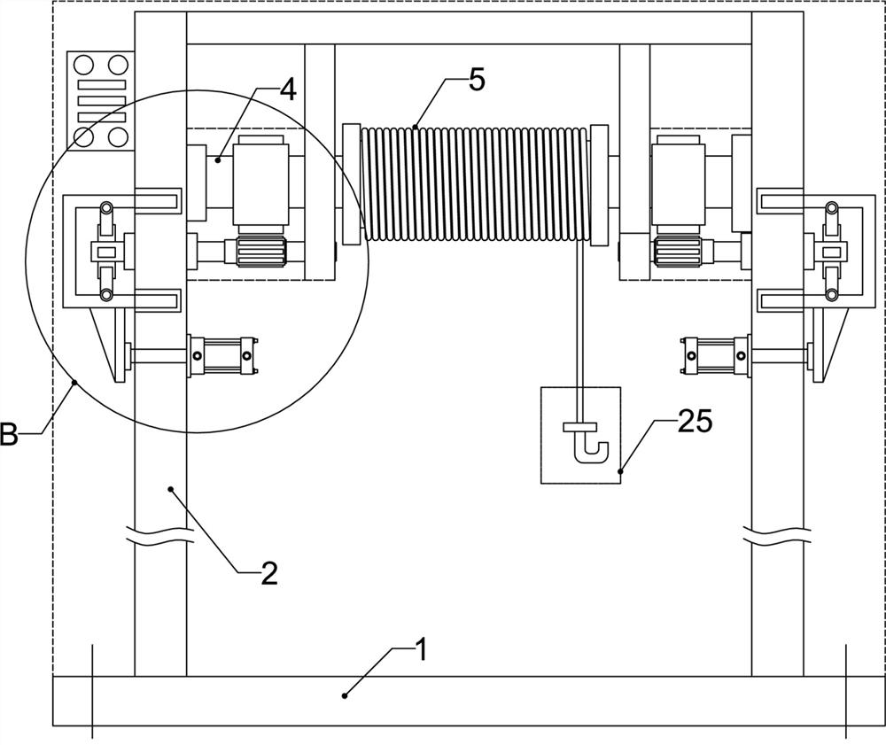
[0039] Embodiment 1: a kind of as figure 1 The crane hoisting intelligent braking device shown not only includes components such as the crane hanger, sling mechanism, and control cabinet, but also includes a set of mechanisms for effectively braking the carrying rod.

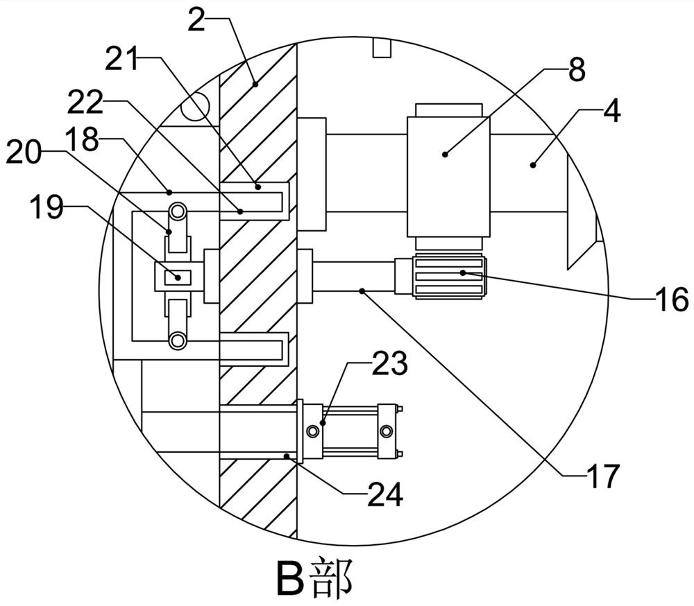
[0040] Specifically, such as figure 1 Among them, the hanger includes a lower base plate and an upper base plate and at least one pair of bearing walls. Between a pair of bearing walls of the crane hanger, a bearing roller is installed through a bearing assembly, and one end of the bearing roller is transmission-connected to a hoisting driving mechanism (not shown in the figure). The sling mechanism installed on the carrying roller includes a hoist, a sling and a hook mechanism, etc., and the sling mechanism can be realized in any form of existing hoisting equipment. At the same time, the bearing roller is connected with the reverse self-locking mechanism through the transmission mechanism. figure 1 It can be...

Embodiment 2

[0050] Embodiment 2: On the basis of Embodiment 1, the similarities will not be repeated. The difference is that the structure of the cylindrical frame of the reverse self-locking mechanism and the structure of the linear drive mechanism are changed.

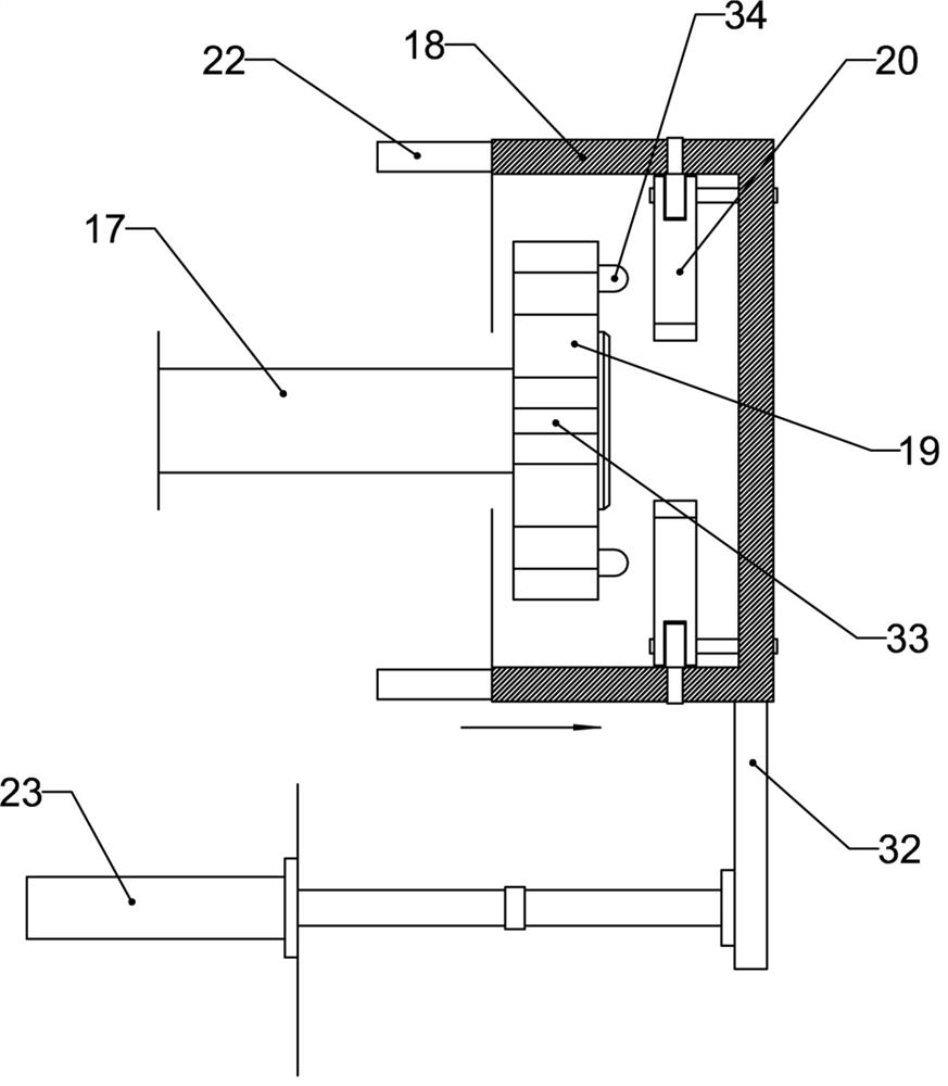
[0051] Specifically, the cylindrical frame is designed as a fixed frame, which is fixed on the outside of the load-bearing wall. Such as Figure 9 As shown, the transmission rod designed with the reverse self-locking mechanism includes a spline shaft and a spline sleeve, which can translate axially and rotate synchronously after being fitted.

[0052] The spline shaft is located at the outer end or the spline sleeve is located at the outer end, and the cam wheel is sleeved on the spline sleeve located at the outer end or is sleeved on the spline shaft. At the same time, there is also a shift fork that drives the spline sleeve or the spline shaft to move axially, such as Figure 9 Among them, the shift fork is set on the outsid...

Embodiment 3

[0056] Embodiment 3: On the basis of Embodiment 1 or 2, the engagement relationship between the convex plate and the limiting plate is designed.

[0057] Specifically, outwardly protruding guide rods are respectively provided on one side of each protruding plate, and the ends of each lead-out rod are fixed as a whole by a support ring, there is a gap between adjacent guide rods, and each limiting plate is inserted into the corresponding gap Inside, each guide rod can move each limit plate clockwise or counterclockwise, and still maintain a clockwise or counterclockwise dumping state after the load roller stops rotating, so that the load roll can pass through the limit plate after it stops rotating. into the gaps between the convex plates.


PUM


Abstract

The invention discloses an intelligent braking device for hoisting a crane, which comprises a crane hanger and a sling mechanism. Between a pair of load-bearing walls of the crane hanger, a load-bearing roller is installed through a bearing assembly and connected in transmission with a hoisting drive mechanism. The roller is connected with the reverse self-locking mechanism through the transmission mechanism, which includes a transmission rod. The cloth is provided with n convex plates, and the inner wall of the cylindrical frame set on the outer end of the transmission rod is sequentially hinged with n limiting plates, so that each limiting plate must be in an inclined state to enter between adjacent convex plates at the corresponding position. In the present invention, when the hoisting driving mechanism stops, the linear driving mechanism controls the reverse self-locking mechanism, so that each limiting plate enters the gap between each convex plate to perform safety braking on the hoisting device, effectively reducing safety threats and making The lifting device moves more smoothly and smoothly.

Description

technical field [0001] The invention relates to the technical field of crane braking, in particular to an automatic and intelligent braking device for crane hoisting. Background technique [0002] Industrial production is inseparable from the operation of cranes. Cranes refer to multi-action hoisting machinery that vertically lifts and horizontally transports heavy objects within a certain range. The working characteristics of cranes are intermittent movements, mainly used for lifting and loading and unloading materials. Including double-girder cranes and cantilever cranes, double-girder cranes are one of many types of cranes. They are composed of two main beams and lifting mechanisms. Lifting equipment with both ends resting on tall concrete columns or metal supports. Double-girder cranes are widely used in workshops, stockyards and warehouses. Compared with single-girder cranes, the lifting height of double-girder cranes is higher than the height of a beam section for a c...

Claims


Application Information

Patent Timeline
Patent Type & Authority Patents(China)
IPC IPC(8): B66C15/00B66C5/02B66C13/46B66C13/48B66D1/14B66D1/48B66D1/54
CPCB66C15/00B66C5/02B66C13/46B66C13/48B66D1/14B66D1/48B66D1/54
Inventor 刘广宇王梦瑜左蓉
Owner 天津市滨海新区检验检测中心
Why Eureka
Try Eureka