Light beam alignment device and alignment method for ultralow-temperature vacuum environment

A technology for aligning devices and vacuum environments, applied in measuring devices, photometry, optical radiation measurement, etc., can solve the problems of difficult alignment and debugging, low precision, etc., and achieve simple structure, high beam alignment accuracy, and applicable The effect of wide wavelength range

Active Publication Date: 2021-08-24
THE 41ST INST OF CHINA ELECTRONICS TECH GRP
View PDF6 Cites 0 Cited by
  • Summary
  • Abstract
  • Description
  • Claims
  • Application Information

AI Technical Summary

Problems solved by technology

[0004] The technical problems to be solved by the present invention are: 1. Propose a beam alignment method and alignment device suitable for ultra-low temperature vacuum environment; 2. The existing beam alignment method based on four-quadrant detectors is only applicable to the 200nm-1100nm band For the shortcomings of beam alignment, a universal beam alignment method without wavelength range limitation is proposed; 3. Aiming at the problems of difficult alignment and debugging and low precision of traditional beam alignment methods, a compact structure and strong versatility are proposed. Advanced beam alignment device, which simplifies the difficulty of alignment debugging and improves alignment accuracy; 4. Realize high-precision alignment of the incident beam without passing through, monitoring stray light, and changing the optical power of the alignment beam, and improving the follow-up light beam. Accuracy of measurements such as power

Method used


Image

  • Light beam alignment device and alignment method for ultralow-temperature vacuum environment
  • Light beam alignment device and alignment method for ultralow-temperature vacuum environment
  • Light beam alignment device and alignment method for ultralow-temperature vacuum environment

Examples


Embodiment 1

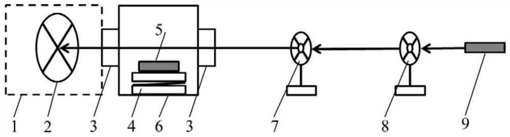
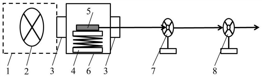
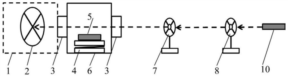
[0029] Such as Figure 1-Figure 3 As shown, one embodiment of the present invention is to propose a beam alignment device for an ultra-low temperature vacuum environment, including: an ultra-low temperature vacuum chamber body 1, an alignment target 2, a vacuum interface 3, a vacuum program-controlled displacement stage 4, and a guide Laser module 5, alignment device vacuum chamber body 6, first aperture 7, second aperture 8, laser module 9 for assembly and adjustment, and working light source 10; among them, vacuum program-controlled displacement stage 4, guiding laser module 5, alignment The vacuum chamber body 6 of the device together constitutes an external beam alignment module.

[0030] In the alignment device, a standard vacuum interface is provided on the same axis before and after the ultra-low temperature vacuum chamber body 1, and a vacuum program-controlled displacement table 4 is installed inside the ultra-low temperature vacuum chamber body 1, and a guiding laser...

Embodiment 2

[0036] On the basis of the above embodiments, the present invention also provides a beam alignment method for an ultra-low temperature vacuum environment, including a method for installing and debugging a beam alignment device and a beam alignment method, specifically including:

[0037] (1) Installation and debugging method of beam alignment device

[0038] The first step is to open the chamber of the ultra-low temperature vacuum device and adjust the position of the laser module before the ultra-low temperature refrigeration and vacuum pumping of the ultra-low temperature vacuum device and the beam alignment device, so that the laser module can be adjusted through the center of each vacuum interface and hit the Align the center of the target;

[0039]The second step is to close the chamber of the ultra-low temperature vacuum device and keep the position constant, set the first aperture and the second aperture in sequence on the optical path of the laser, and fix the position...


PUM


Abstract

The invention provides a light beam alignment device and alignment method for an ultralow-temperature vacuum environment. The device comprises an ultralow-temperature vacuum bin body, an alignment target, a vacuum interface, a vacuum program control displacement table, a guide laser module, an alignment device vacuum bin body, a first diaphragm, a second diaphragm, an adjustment laser module and a working light source. The device has the advantages that: 1, no complex optical path or circuit is needed, the structure is simple, and the use is convenient; 2, the applicable wavelength range is wide, and wavelength limitation is avoided; 3, the light beam alignment precision is high; and 4, the incident light power is not changed in the alignment process, stray light is not introduced, and the test precision of subsequent light power measurement and the like is not influenced.

Description

technical field [0001] The invention belongs to the technical field of beam alignment, and in particular relates to a beam alignment device and an alignment method used in an ultra-low temperature vacuum environment. Background technique [0002] Beam alignment is an important problem in the process of optical precision measurement and optical metrology, especially when it involves the alignment of non-visible light beams in special environments such as ultra-low temperature vacuum, the alignment is more difficult. The existing beam alignment method generally uses a four-quadrant detector supplemented by related reflection, spectroscopic and other optical devices, and judges the beam alignment by monitoring the readings of the four-quadrant detector. Since most of the four-quadrant detectors are Si detectors, they can only be used for beam alignment in the 200nm-1100nm band. For other wave bands such as ultraviolet and infrared, the existing method generally uses a 632.8nm ...

Claims


Application Information

Patent Timeline
Patent Type & Authority Applications(China)
IPC IPC(8): G01J1/02G01J1/04
CPCG01J1/0266G01J1/0411
Inventor 庄新港史学舜刘红博张鹏举刘长明赵发财沈荣仁
Owner THE 41ST INST OF CHINA ELECTRONICS TECH GRP
Why Eureka
Try Eureka