Supercharge Your Innovation With Domain-Expert AI Agents!

Efficient paint spraying device for manufacturing and machining engineering machine

A kind of construction machinery and high-efficiency technology, which is applied in the direction of spraying device, spray booth, and surface coating liquid device, etc. It can solve the problems of inability to realize double-sided spraying operation, uneven paint coverage, spraying dead angle, etc., and achieve high efficiency and convenience Double-sided spraying, avoiding dead ends of spraying, and ensuring uniformity

Inactive Publication Date: 2021-08-27
邓兰
View PDF8 Cites 6 Cited by
  • Summary
  • Abstract
  • Description
  • Claims
  • Application Information

AI Technical Summary

Problems solved by technology

[0004] The spraying equipment in the prior art has the following disadvantages in the actual working process: when the workpiece is sprayed, it is generally sprayed on one side, and efficient double-sided spraying operation cannot be realized. Therefore the present invention proposes a kind of high-efficiency paint spraying device for engineering machinery manufacturing and processing here

Method used


Image

  • Efficient paint spraying device for manufacturing and machining engineering machine
  • Efficient paint spraying device for manufacturing and machining engineering machine
  • Efficient paint spraying device for manufacturing and machining engineering machine

Examples


Embodiment 1

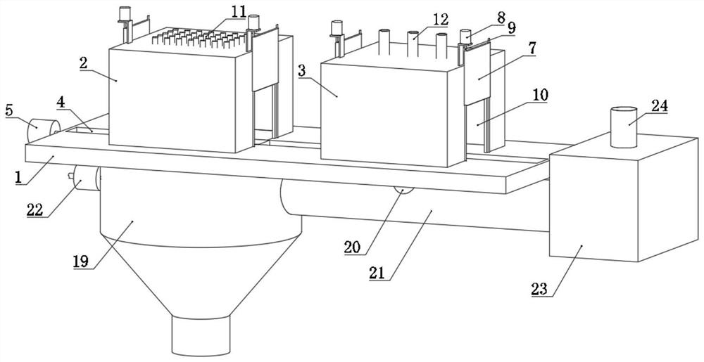
[0036] refer to Figure 1-8 , a high-efficiency painting device for construction machinery manufacturing and processing, including a substrate 1, a track groove 4 is opened on the top surface of the substrate 1, and a spraying box 2 and a drying box are respectively installed on the top surface of the substrate 1 and located at the front and rear sides of the track groove 4 3. The spraying box 2 and the drying box 3 are provided with a door opening 10 at the position corresponding to the track groove 4, and the door opening 10 is movably equipped with a door panel 7,

[0037] The door opening 10 and the door panel 7 size of the spraying box 2 places are equal to the door opening 10 and the door panel 7 size of the drying box 3 places. Wherein the size of the door panel 7 is slightly larger than the size of the door opening 10 to ensure that the door panel 7 can completely seal and cover the door opening 10 .

[0038] The front side of the door panel 7 is threaded with a lifti...

Embodiment 2

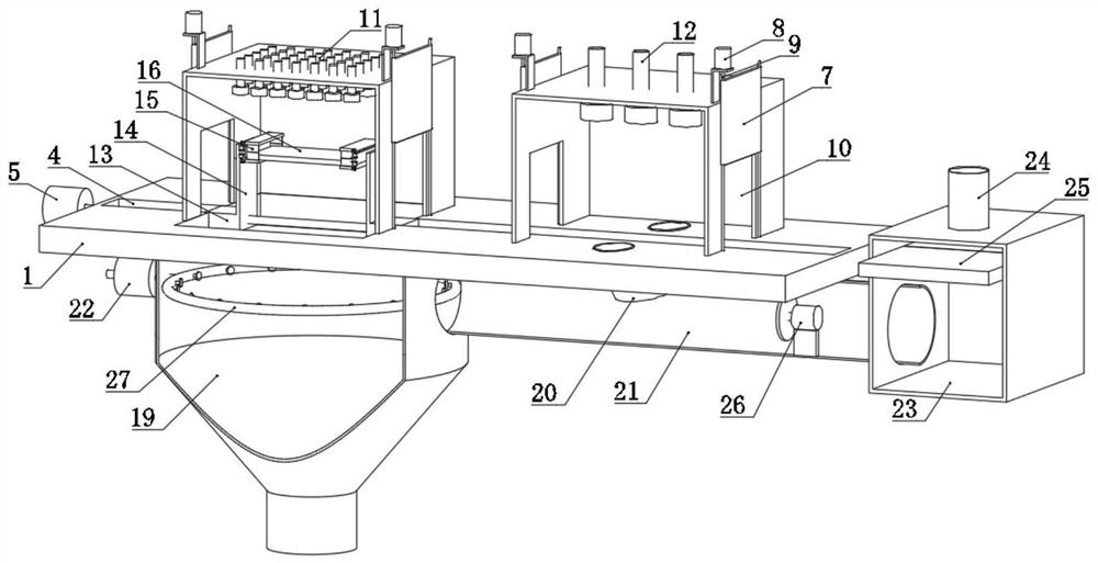
[0047] refer to Figure 1-8 In this second embodiment, on the basis of the first embodiment above, two rectangular grooves 17 are provided at the positions corresponding to the spraying box 2 on the substrate 1, and the two rectangular grooves 17 are symmetrically distributed on both sides of the track groove 4, and the substrate 1 Two air holes 18 are provided at the position corresponding to the drying box 3, and the two air holes 18 are symmetrically distributed on both sides of the track groove 4, and a purification box 19 is installed at the position corresponding to the two rectangular grooves 17 on the bottom surface of the substrate 1 to purify The bottom of case 19 is bucket-shaped and is equipped with drainpipe, and drainpipe is equipped with valve. The inner wall of the top of the purification box 19 is equipped with a circular pipe 27, the circular pipe 27 is connected with the water pump 22 through a pipeline, the water pump 22 is externally connected to the water...


PUM


Abstract

The invention discloses an efficient paint spraying device for manufacturing and machining an engineering machine, and belongs to the field of mechanical spraying. The efficient paint spraying device comprises a base plate, wherein a rail groove is formed in the top surface of the base plate, and a spraying box and a drying box are mounted on the top surface of the base plate and located on the front side and the rear side of the rail groove correspondingly. Door openings are formed in the positions, corresponding to the rail groove, of the spraying box and the drying box, and door plates are movably mounted in the door openings, Paint spraying pipes are mounted at the top of the spraying box, and drying pipes are mounted at the top of the drying box. A conveying threaded rod is rotationally installed in the rail groove. A conveying motor is installed at one end of the base plate, the driving end of the conveying motor is installed at one end of the conveying threaded rod, and two sealing bases are arranged in the rail groove. According to the efficient paint spraying device for manufacturing and machining the engineering machine, efficient and convenient double-sided spraying of workpieces can be achieved, spraying dead corners are avoided, and spraying uniformity is guaranteed; and in addition, waste gas wind generated during paint spraying and drying is subjected to adsorption precipitation and adsorption purification treatment, and air pollution is avoided.

Description

technical field [0001] The invention relates to the technical field of mechanical spraying, in particular to a high-efficiency painting device for engineering machinery manufacturing and processing. Background technique [0002] Spraying refers to a coating method in which a spray gun or a disc atomizer is used to disperse into uniform and fine mist droplets by means of pressure or centrifugal force and apply them to the surface of the object to be coated. It can be divided into air spraying, airless spraying, electrostatic spraying and various derived methods of the above basic spraying forms, such as large flow and low pressure atomization spraying, thermal spraying, automatic spraying, multi-group spraying, etc. [0003] After retrieval, Chinese Patent No. CN 211838719 U discloses a paint spraying device for construction machinery manufacturing and processing, including support feet and a net chain conveyor belt. The front surface of the painting box is fixed with an ope...

Claims


Application Information

Patent Timeline
IPC IPC(8): B05B16/20B05B13/02B05B14/43B05D3/02
CPCB05B16/20B05B13/0221B05B14/43B05D3/0254
Inventor 邓兰
Owner 邓兰
Features
  • R&D
  • Intellectual Property
  • Life Sciences
  • Materials
  • Tech Scout
  • Unparalleled Data Quality
  • Higher Quality Content
  • 60% Fewer Hallucinations
Learn More