Computer case punch forming device and using method thereof

A stamping forming, computer technology, applied in the field of stamping devices

Inactive Publication Date: 2021-08-27
京山亿捷电脑有限公司
View PDF1 Cites 2 Cited by
  • Summary
  • Abstract
  • Description
  • Claims
  • Application Information

AI Technical Summary

Problems solved by technology

[0003] After retrieval, the Chinese patent application number is CN201920328007.4, which discloses a computer case stamping device, including: a base, a lower mold fixing bar, a stamping cylinder, an upper mold fixing plate, a punch and a die, the base The upper surface of the seat is provided with the lower mold fixing strip, the die is placed in the U-shaped area surrounded by the lower mold fixing strip, and the side wall of the lower mold fixing strip is installed with a The top wire of the above-mentioned die, but the above-mentioned technical solution is not equipped with a corresponding mechanism that can absorb and fix the chassis plate on the lower mold, so it is easy to remove the chassis on the lower mold during the upward movement process after the stamping of the upper mold is completed. The problems caused by the plank

Method used


Image

  • Computer case punch forming device and using method thereof
  • Computer case punch forming device and using method thereof
  • Computer case punch forming device and using method thereof

Examples


Embodiment 1

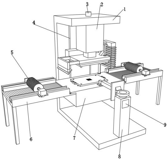
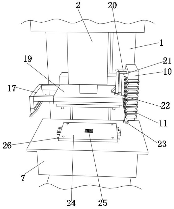
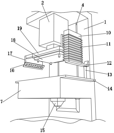
[0042] A stamping and forming device for a computer case, such as Figure 1-9 As shown, it includes an installation frame 1, the top outer wall of the installation frame 1 is provided with a warning light 3, the top inner wall of the installation frame 1 is provided with a hydraulic push rod 2, the bottom inner wall of the installation frame 1 is provided with a column 8, and the outer wall of one side of the column 8 is provided with a The control panel 9 and the outer wall on one side of the column 8 are provided with a manipulator mechanism, and the inner wall on one side of the installation frame 1 is provided with a support platform 7 . Two electric transmission plates 6 are arranged on the outer walls of both sides of the support table 7, the output shaft of the hydraulic push rod 2 is provided with a pressing plate 19, the outer wall of the bottom of the pressing plate 19 is provided with an upper mold 18, the outer wall of the top of the pressing plate 19 is provided wi...

Embodiment 2

[0055] A method for using a stamping and forming device for a computer case, such as Figure 1-9 shown, including the following steps:

[0056] S1: Place the plate on the electric conveying plate 6, and control the electric conveying plate 6 through the control panel 9 to drive the plate to the side of the support table 7;

[0057] S2: Control the mechanical arm mechanism through the control panel 9 to grab the plate on the electric transfer plate 6, and place the plate on the lower mold 24 located on the outer wall of the top of the support table 7;

[0058] S3: Control the hydraulic push rod 2 through the control panel 9 to push the pressure plate 19 down, and drive the upper mold 18 at the bottom of the pressure plate 19 to stamp the plate on the top of the lower mold 24;

[0059] S4: After the stamping is completed, the control panel 9 controls the hydraulic push rod 2 to reset, and controls the manipulator mechanism to grab the plate on the top of the lower mold 24;

[...


PUM


Abstract

The invention discloses a computer case punch forming device and a using method thereof, relates to the technical field of punching devices, and aims to solve the problem that after punching of an upper die is finished, a case plate on a lower die is easily lifted up in the upward moving process. The device specifically comprises a mounting frame, a warning lamp is arranged on the outer wall of the top of the mounting frame, a hydraulic push rod is arranged on the inner wall of the top of the mounting frame, a stand column is arranged on the inner wall of the bottom of the mounting frame, and a control panel is arranged on the outer wall of one side of the stand column. The using method of the device specifically comprises the steps that a plate is placed on an electric conveying plate, and the electric conveying plate is controlled by the control panel to drive the plate to one side of a supporting table. An extrusion block, an air bag, a first air guide pipe, a second air valve and an adsorption plate are arranged, after the plate is punched, a pressing plate moves upwards through the hydraulic push rod to be reset, at the moment, a connecting rod pushes the extrusion block to move upwards, and therefore the air bag is stretched.

Description

technical field [0001] The invention relates to the technical field of punching devices, in particular to a punching forming device for a computer case and a method for using the same. Background technique [0002] Among the components of the computer, the computer case is a very important part of the computer accessories. Its main function is to place and fix various computer accessories, and play a role of support and protection. In addition, the computer case plays an important role in shielding electromagnetic radiation. The chassis generally includes a shell, a bracket, various switches on the panel, indicator lights, etc. The shell is made of steel plate and plastic, with high hardness, mainly to protect the internal components of the chassis. During the production process of the chassis, a stamping process is performed to process the holes on the surface of the chassis. [0003] After retrieval, the Chinese patent application number is CN201920328007.4, which discl...

Claims


Application Information

Patent Timeline
Patent Type & Authority Applications(China)
IPC IPC(8): B21D22/06B21D45/00B08B1/02B08B5/02B08B15/04B01D46/10
CPCB01D46/10B08B1/02B08B5/02B08B15/04B21D22/06B21D45/00
Inventor 候斌刘伟
Owner 京山亿捷电脑有限公司
Why Eureka
Try Eureka